
12 Volt Power Supplies
LM7812 power supply schematic A very simple PS circuit with the basic 3 Amper version of LM7812 IC.
LM317 variable power supply circuit
2N3055 adjustable power supply schematic This PS circuit has a over-current protection and a good stabilized voltage. It can deliver up to 1.6 A.
The description outlines four distinct 12V DC power supply circuits, each designed to deliver stable output voltages around 12V. The first circuit utilizes a BD139 transistor in conjunction with a zener diode and several passive components. This configuration allows for straightforward construction and reliable operation, provided that the maximum ratings of the components are adhered to.
The second circuit employs the LM7812 voltage regulator IC, which is a widely used component for providing a fixed output voltage of 12V. This particular circuit is designed for a current output of up to 3 Amperes, making it suitable for moderate power applications.
The third circuit features the LM317 adjustable voltage regulator. This device is capable of providing variable output voltages, which can be set to 12V by selecting appropriate resistor values in the feedback network. The LM317 is a versatile component that allows for customization depending on the specific requirements of the circuit.
Finally, the fourth circuit is based on the 2N3055 power transistor, which is known for its ability to handle higher current loads. This adjustable power supply includes over-current protection features, ensuring that the output voltage remains stable while preventing damage to the circuit in case of excessive current draw. It is capable of delivering up to 1.6 Amperes, making it suitable for applications requiring more power.
Each of these circuits provides a unique approach to obtaining a 12V DC power supply, catering to various needs and applications while maintaining simplicity in design and construction.4 simple 12Vdc power supply circuits with output voltages around 12V. First power supply circuit is built with BD139, one zener diode and a few passive components. Each of the schematic is very simple to construct and will function without problems if you respect the maximum power supply ratings. 12V BD139 power supply circuit LM7812 power supply schematic A very simple PS circuit with the basic 3 Amper version of LM7812 IC. LM317 variable power supply circuit 2N3055 adjustable power supply schematic This PS circuit has a over-current protection and a good stabilized voltage.
It can deliver up to 1.6 A. 🔗 External reference
Related Circuits
The circuit comprises an N-MOSFET voltage follower (T1, common drain) and a current source (T2, NPN Darlington). The current source is set to 2.2 Amps. With a supply voltage of 40V, the circuit can deliver approximately 17W into an...
The "R-h sampling circuit limit order" aims to reduce the sampling resistor. A DC voltage level can be positioned between the components. The circuit includes a line amplifier that allows for magnification adjustments and is designed to protect against...
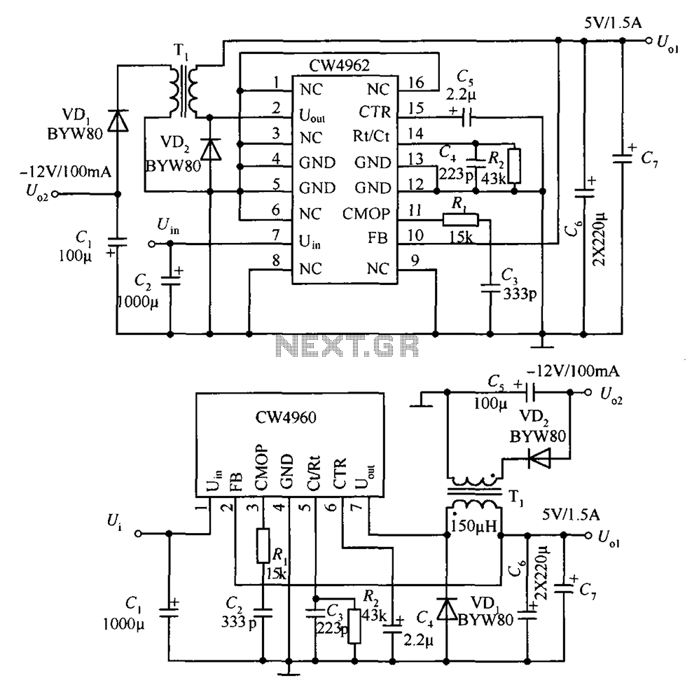
The circuit described is a stabilized power supply utilizing the CW4962 and CW4960 components, providing +5V at 1.5A and -12V at 100mA. The +5V output serves as the main power supply. The output circuit employs a transformer rather than...
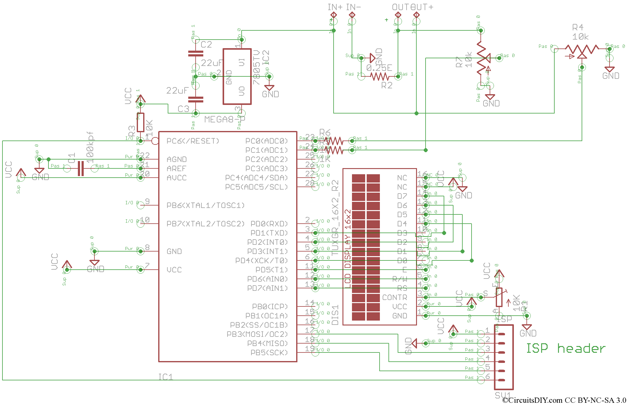
This is the V2 update of the Atmega8 Volt-Ammeter. This new version features several upgrades, including low power consumption, improved amperage display resolution while using a low-value drop resistor, and a much smaller PCB size of only 5cm x...
There are two systems of pneumatic central locking in vintage Audis. Earlier models are controlled by the driver's door lock, while later models use both front door locks. The earlier models (5000/100/200 before 1984, 4000/Coupe/Quattro/80/90 before 1988) utilize a...
This simple circuit is a good solution to the powering a dual supply op amp from a single battery problem. The circuit simply takes a positive voltage and inverts it. It uses only one 555 timer and a few...