
120 VAC Lamp Dimmer

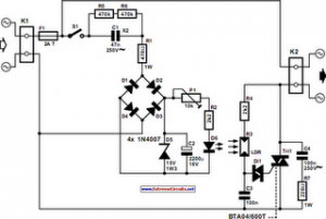
This circuit operates by utilizing the principles of phase control to regulate power delivery to the load. The four diodes are arranged in a bridge rectifier configuration, ensuring that the AC input voltage is converted into a pulsating DC voltage. This rectified voltage is applied to the anode of the SCR, which is a semiconductor device capable of controlling large amounts of power.
The role of the 2.2 µF capacitor is critical in this design. It serves to smooth out the voltage fluctuations and acts as a timing element for the circuit. The small signal transistors, typically NPN types, are configured in such a way that they act as a switch. When the voltage across the capacitor reaches the threshold of 8 volts, the transistors turn on, creating a path for the capacitor to discharge. This discharge occurs through the gate of the SCR, triggering it into the conducting state.
Once the SCR is triggered, it remains in the 'on' state until the current flowing through it drops below a certain level, known as the holding current. This allows the SCR to control the power delivered to the load effectively. The phase control aspect enables the adjustment of the conduction angle of the SCR, which in turn regulates the amount of power supplied to the load.
Overall, this full-wave phase control circuit exemplifies an efficient method of controlling AC power using semiconductor devices, and its design principles remain applicable in various modern applications such as light dimmers, motor speed controllers, and heating elements.The full wave phase control circuit below was found in a RCA power circuits book from 1969. The load is placed in series with the AC line and the four diodes provide a full wave rectified voltage to the anode of a SCR. Two small signal transistors are connected in a switch configuration so that when the voltage on the 2.2uF capacitor reaches about 8 volts, the transistors will switch on and discharge the capacitor through the SCR gate causing it to begin conducting
🔗 External reference
Related Circuits

This circuit produces a soft turn-on for halogen lamp filaments upon powering up. The MOSFET used is a BUZ10, which has a resistance of 0.2 ohms. Resistors R1, R2, and capacitor C1 set the turn-on rate, while diode D1...
As you know the AT90S1200 microcontroller includes an internal RC oscillator that is disabled by default. If you want to change it (enable or disable) you must program it with parallel mode. Most programmers work with serial mode and...

This device allows one or more lamps to illuminate at sunset and turn off at dawn. Q1 and Q2 form a trigger device for the SCR, providing short pulses at 100Hz frequency. Pulse duration is set by R2 and...
The following circuit illustrates an Automatic Light Dimmer Circuit Diagram utilizing a 1N4007 diode. Features include integration within a wall-mounted box. The Automatic Light Dimmer Circuit is designed to adjust the brightness of a light source automatically based on ambient...
This circuit serves as a dependable alternative to thermally-activated switches designed for flashing Christmas tree lamps. The arrangement consisting of Q1, Q2, and associated resistors activates the silicon-controlled rectifier (SCR). The timing function is determined by resistors R1, R2,...
The development of a solar energy street lamp control device has progressed through three stages. The first generation featured a simple and crude function, allowing the light to be turned on or off, but required connection to a light-sensitive...