
AC 220 Volts Flashing Lamps Circuit
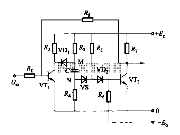
This circuit utilizes a combination of transistors (Q1 and Q2) and resistors to control the operation of an SCR, which is pivotal in managing the power delivered to the lamp. The transistors are configured to form a trigger circuit that activates the SCR when a specific voltage level is reached. The resistors R1 and R2, along with capacitor C1, form an RC timing circuit that dictates the frequency of the flashing lamps.
The timing capacitor C1 plays a crucial role in determining how long the SCR remains conductive during each cycle. By varying the capacitance of C1, the time constant of the RC circuit changes, thus altering the frequency of the flashing effect. It is essential to maintain the values of R1 and R2 constant to ensure stable operation, as they set the thresholds for the triggering mechanism of the transistors.
In practical applications, the circuit can be powered by a standard AC supply, and the SCR can handle the load of the Christmas tree lamps efficiently. The design ensures that the flashing effect is visually appealing and can be adjusted to suit different aesthetic preferences by simply changing the capacitor value. This makes it an ideal solution for holiday lighting applications where reliability and ease of use are paramount. Proper heat dissipation measures should also be considered to ensure the longevity of the components involved, particularly the SCR, which can generate heat during operation.This circuit is intended as a reliable replacement to thermally-activated switches used for Christmas tree lamp-flashing. The device formed by Q1, Q2 and related resistors triggers the SCR. Timing is provided by R1, R2 & C1. To change flashing frequency do not modify R1 and R2 values: set C1 value from 100 to 2200µF instead..
🔗 External reference
Related Circuits
This amplifier circuit is designed to enhance TV signals in the UHF range. It employs a low-noise transistor, providing an amplification of 10 to 15 dB within the frequency spectrum of 400 MHz to 850 MHz. It is crucial...
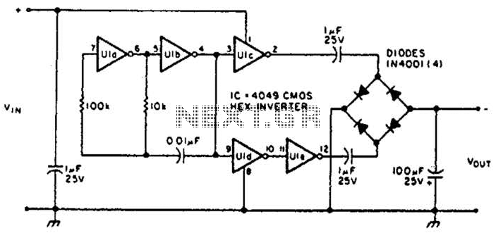
This circuit will provide a negative DC voltage that is approximately equal to the positive input voltage at no load and about 3 V less at a 10 mA load. The input voltage range is from +5 to +15...
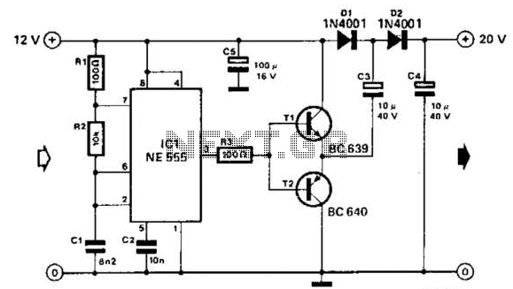
Using a 555 timer and voltage doubler, this circuit will supply over 50 mA at 20 V DC. Transistors T1 and T2 act as power amplifiers to drive the voltage doubler. The frequency of operation is approximately 8.5 kHz. The...
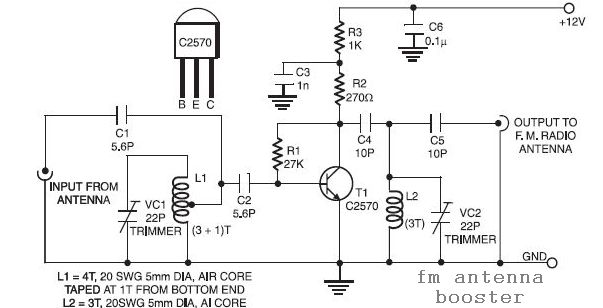
The input coil L1 is composed of four turns of 20 SWG enamelled copper wire, wound slightly spaced over a 5mm diameter former. It is tapped at the first turn from the ground lead side. Coil L2 is similar...
Discharge before memory circuit. Before the memory circuit is activated, a delay reset circuit is required. When the input signal triggers an action, timing begins, and after a specified delay, the circuit reverts to its original state. During this...
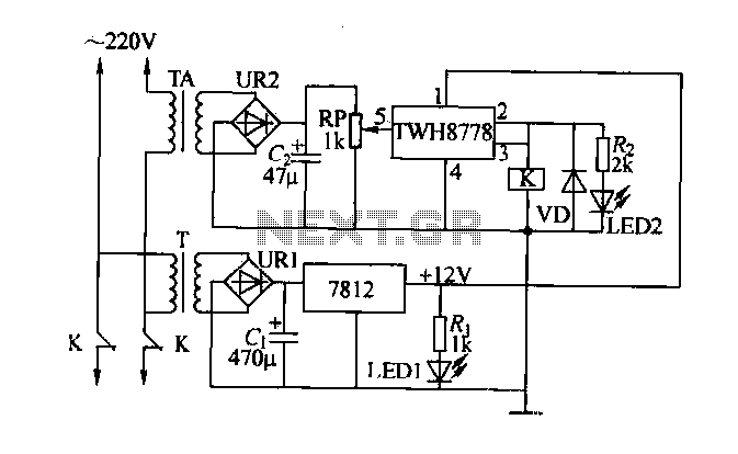
An electric power limiter circuit restricts the user load, ensuring that household appliances operate within a specified normal current range. When the load exceeds a predetermined threshold, the power supply is disconnected. This circuit utilizes the high-power integrated TWH8778...
Warning: include(partials/cookie-banner.php): Failed to open stream: Permission denied in /var/www/html/nextgr/view-circuit.php on line 713
Warning: include(): Failed opening 'partials/cookie-banner.php' for inclusion (include_path='.:/usr/share/php') in /var/www/html/nextgr/view-circuit.php on line 713