
Automatic Light DimmerCircuit Using 1N4007 Diode
The Automatic Light Dimmer Circuit is designed to adjust the brightness of a light source automatically based on ambient light conditions. The core component, the 1N4007 diode, serves as a rectifier within the circuit. This diode is known for its high reverse voltage capability and robustness, making it suitable for various electronic applications.
The circuit typically includes a light-dependent resistor (LDR) which detects the intensity of light in the environment. When the ambient light level decreases, the resistance of the LDR increases, triggering the dimming function. A transistor is often used to control the light’s intensity based on the voltage drop across the LDR. As the LDR's resistance changes, it affects the base current of the transistor, allowing it to either conduct more or less current to the connected light source, thereby dimming or brightening the light as needed.
Additionally, a potentiometer may be integrated into the circuit to allow manual adjustment of the sensitivity of the LDR, providing users with the flexibility to set the dimming threshold according to their preferences. The entire assembly is typically housed in a wall-mounted box for aesthetic integration into home or office environments.
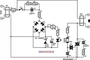
This Automatic Light Dimmer Circuit is particularly beneficial in energy conservation, extending the life of light bulbs, and enhancing the comfort of indoor lighting by providing a more adaptable lighting solution.The following circuit shows about Automatic Light Dimmer Circuit Diagram using 1N4007 Diode. Features: built into a wall-mounted box containing . 🔗 External reference
Related Circuits
The circuit comprises two sections: charger power supply and LED driver. The charger power supply section is built around a 3-terminal adjustable regulator (IC1) LM317, while the LED driver section is built around transistor BD140 (T2). In the charger...
The circuit was designed to provide an adjustable power supply that is symmetrically configured, offering a voltage range from 1.25V to 30V at a current output of 1A. The adjustable power supply circuit is typically composed of several key components...
This solar birdhouse light features an economical circuit for a mini solar lighting system. The core component of the circuit is a mini 6V/2W solar panel, which is utilized to charge a 4V/800mAh rechargeable battery. The charging process is...
The switch control system utilizes sensors to inform the microcontroller of the trains' positions on the layout. This ensures that only one train occupies the main line at any given time and that switches are correctly set for the...
A simple calculator, in conjunction with a chip-on-board (COB) from an analogue quartz clock, is utilized to create a telephone call meter. The calculator facilitates the conversion of STD/ISD calls into local call equivalents and consistently displays the current...
This is a measurement I did on a FM receiver (MC3372). I have plotted the output DC-bias as a function of the IF (Intermediate Frequency) frequency. At 455kHz you can see that I have 5.5V DC bias. When I...