
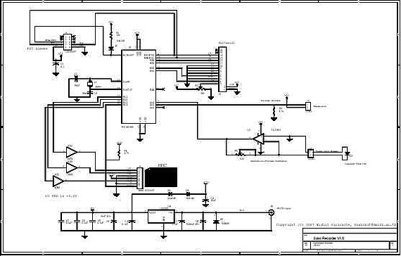
12F675 based Brushed Motor ESC
This project involves the design and assembly of a Brushed Motor ESC tailored for remote-controlled cars and boats, leveraging the capabilities of the Microchip 12F675 PIC microcontroller. The circuit incorporates a few standard electronic components, including resistors, capacitors, and transistors, arranged to facilitate the control of motor speed and direction. The ESC is designed to handle the unique operational demands of automotive and marine applications, which often require precise throttle control and the ability to reverse and brake.
The core functionality of the ESC is achieved through the use of the PIC microcontroller, which processes input signals from the throttle control and translates them into appropriate PWM (Pulse Width Modulation) signals to control the motor. The programming interface is user-friendly, allowing for easy adjustments to the ESC's parameters via a push button and an LED indicator. This interface is crucial for configuring settings such as brake-to-reverse delay, which enhances the responsiveness of the vehicle.
The EEPROM within the PIC microcontroller plays a vital role in retaining user-defined settings, ensuring that they persist across power cycles. This feature is particularly beneficial for users who frequently operate their vehicles, as it eliminates the need for repeated configuration. The ESC's safety mechanisms, which prevent it from arming unless the throttle is in the neutral position, add an additional layer of reliability, reducing the risk of accidental activation.
The design process includes the utilization of the MPLAB IDE, where users can customize the firmware to suit their specific ESC requirements. This approach allows for flexibility in software development, enabling users to select various operational parameters tailored to their unique setups. It is recommended that users establish a concise directory for their project files, as the IDE has limitations on path length, which could affect functionality.
In summary, this Brushed Motor ESC project provides a comprehensive solution for enthusiasts looking to enhance their remote-controlled vehicles with advanced speed control features. By combining a robust microcontroller with a straightforward programming interface, the design facilitates an engaging and customizable experience for users in the automotive and marine domains.This project documents how to build and construct your own Brushed Motor ESC for Cars and Boats using a Microchip 12F675 PIC and a small number of standard components. This ESC grew out of an earlier aircraft ESC. A number of people asked for an ESC with brake and reverse operations that were suited to Car and Boat operations.
While the earlier de sign provided basic reverse facilities I decided not to extend the aircraft design, but rather to revise the design and produce a project targeted specifically at cars and boats. This ESC operates in a very similar manner to the Team Tekin "Rebel 2" ESC and offers all of the key features of the earlier aircraft ESC as well as push-button programming.
This ESC has a push button and LED that permit the ESC to be configured. The configuration is stored in the EEPROM on the PIC and will stay set until reconfigured. On power up the ESC will not arm until the throttle is in the neutral position. It is possible to perform throttle configuration during this time using the configuration system (see below). The ESC also requires the throttle to be in the neutral position to rearm the ESC after: It is almost certain that you will need to perform throttle configuration the first time that you use the ESC.
This is because it is very unlikely that the factory default options in the ESC will match your radio control unit. To set the brake to reverse delay period press the `program` switch and keep it pressed for the delay period required and the release the button.
When the button is first pressed the LED will start to flash on and off rapidly. The maximum delay time that can be configured is approximately 5 seconds, after 5 seconds the LED will show a short on flash and a long off flash. If the button is released during this time the maximum 5 second delay is configured. To disable reverse in the ESC press the `program` button and keep it pressed. At first the LED will flash on and off rapidly. Then, after about 5 seconds the LED will change to a short on flash and a long off flash, keep pressing the burron.
After another 5 seconds the LED will alter to a long on flash and long off flash, now release the button. Press the `program` button and hold it down. At first the LED will flash on and off rapidly. Then, after about 5 seconds the LED will change to a short on flash and a long off flash, keep holding the burron down.
After another 5 seconds the LED will alter to a long on flash and long off flash, keep holding the button down. The LED will continue to flash on and off rapidly. Pull the throttle to the full forward direction and hold it there for a few seconds and then return the throttle to the neutral position.
The LED will change to flashing with a long on and long off, this indicates that the forward throttle settings have been configured. Push the throttle to the full brake/reverse position and hold it there for a few seconds and then return the throttle to the neutral position.
If you plan to use this ESC design and build one yourself you will need to download the MPLAB IDE. There are too many ESC options for all the versions to be available on this Web page. With the earlier aircraft design I provided a few `common` versions of the software, however, with this ESC I have assumed that anyone building the ESC will select the options and assemble the code for themselves. Create a directory somewhere on your Windows system. the MPLAB IDE does not like path names that are too long (greater than 30 characters or so) - so stick to a simple short name.
For example: C:PICCarESC 🔗 External reference
Related Circuits
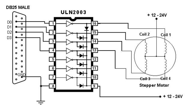
This article outlines the process of connecting a stepper motor to a computer's parallel port and writing code to control it using the scroll wheel of a mouse. For those unfamiliar with stepper motors, this project offers an engaging...
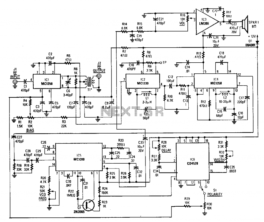
This circuit includes an amplifier and a video detector along with a secondary subcarrier detector for synchronization recovery. A pulse-former circuit modulates the gain of the main channel, enhancing it during synchronization intervals. Additionally, there is a provision for...
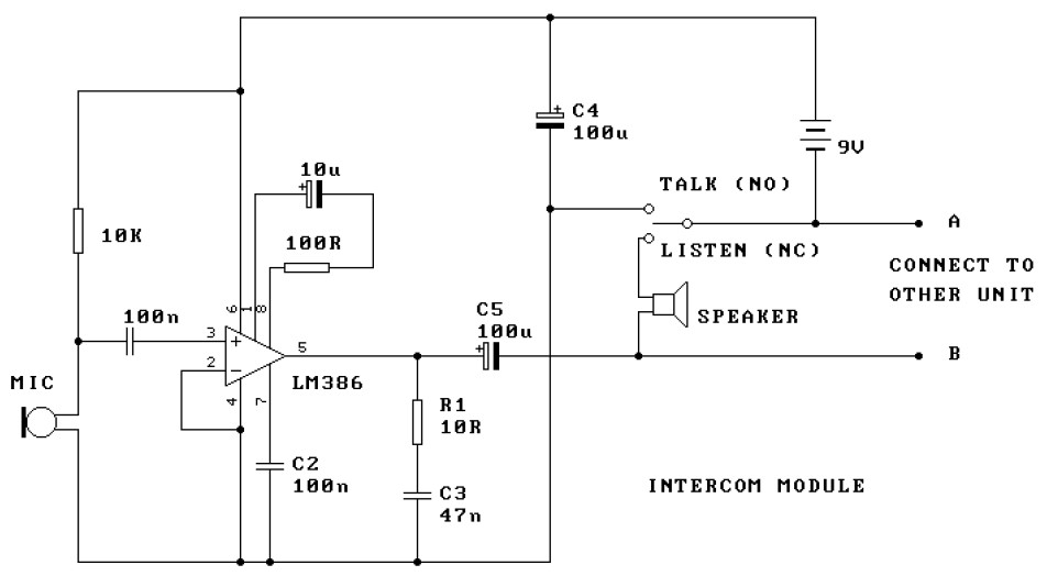
This is a two-station intercom system that operates using two wires connecting each intercom unit. Each unit is self-contained, equipped with its own battery, speaker, microphone, and amplifier circuit. An LM386 audio power amplifier is utilized, which is widely...
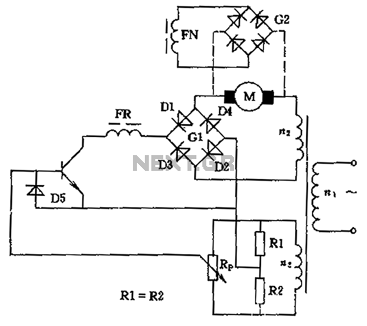
The circuit is designed to control the speed and direction of low-power DC motors, including series and shunt motors. It utilizes a rectifier bridge (G1) connected in series with the motor and linked to the secondary winding (n2) of...
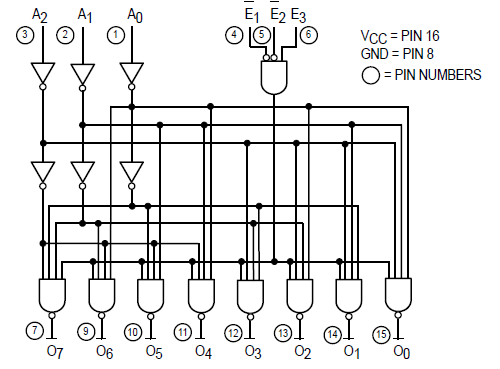
The Motorola SN54/74LS138 is recognized as a 1-of-8 decoder or demultiplexer, specifically engineered for high-speed bar memory chip select address decoding. The accompanying diagram illustrates the logic configuration of the SN54/74LS138 demultiplexer. According to the SN54 datasheet, the multiple...
A device for measuring daily insolation has been developed. The device is constructed using a PIC18F458 microcontroller and a 128MB Multimedia Memory Card (MMC). The insolation measurement device leverages the capabilities of the PIC18F458 microcontroller, which is known for...