
12ft GPS Wall Clock

The 12-foot tall clock project showcases an innovative approach to large-scale LED display design. The integration of GPS technology for automatic time-setting enhances the functionality of the clock, making it not only visually striking but also precise. The use of pre-packaged LED light bars significantly reduces the complexity and labor involved in creating a large LED display, as they are designed for easy assembly and operation. The choice of 12V operation is standard in many LED applications, providing a balance between brightness and energy efficiency.
The decision to diffuse the intense LED light is critical to creating a visually appealing display. The Styrene and Styrofoam light boxes effectively minimize hot spots and provide a uniform light distribution across the digits, enhancing readability from a distance. This is particularly important for a clock of this size, where visibility is paramount.
The construction method, which involves creating separate digits, not only simplifies the manufacturing process but also allows for modularity in design. Each digit can be produced independently, enabling easier repairs or replacements if necessary. The use of Cat5 cables for wiring is a practical solution, leveraging existing technology to facilitate connections while maintaining a tidy and organized appearance.
Overall, this project exemplifies the intersection of creativity and engineering, resulting in a large-scale, functional art piece that effectively utilizes modern LED technology and design principles. The thoughtful consideration of materials, methods, and technologies involved in the clock’s construction contributes to its success as both a timekeeping device and a striking visual installation.We discussed creating a 6` tall alarm clock - authentic down to the Timex face plate. While this may sound like a silly idea to begin with, it quickly became obvious just how difficult it would be to build at that scale so the project was scuttled. Recently, I came across a source for pre-package LED light bars that rejuvenated my need for a big clock. Why not So here is the little project that grew to 12 feet. We added a GPS receiver so now we have a 12` clock that sets itself, displays hours/minutes/seconds, and is accurate to 100ns. Beat that bed side alarm! These light bars, as I like to call them, use three LEDs and run on 12V. Why use them They come pre-packaged with current limiting resistors and nice plastic carriers. This made it easy to create arrays of a large number of super-bright LEDs, without all the hassle and labor of creating our own custom configuration.
Each stick uses about 30mA @ 12V. This is actually pretty good considering how bright they are. 30mA is a fraction of what an equivalent neon tube would pull. It started out as just hours and minutes. Then it was obvious we needed a colon. Then the seconds were so cool that we just had to have them, so in the end, it was two colons and 6 digits. In all: 2. 76Amps! At 12V is ~33Watt power supply. This is not small by any means. Come to mention it - perhaps we could use an ATX power supply. Hmm. Maybe later. At this time, we are using a basic variable bench power supply from Mastech, the HY1803D. With an 18V 3A max output, it handles the 12V @ 3A requirement easily. Originally I was going to simply screw the light bars onto the wall in a 7-segment digit configuration.
That`s where things turned south. The LED bars are fabulous! But the LED intensity is so high, it`s painful to look at. So we needed to diffuse the LED light a bit and create a better shape to the light. Shopping at the local Home Depot produced a large selection of potential options. Using a Styrene sheet of plastic (commonly used with 24x48" fluorescent panel ceilings) l was able to get rid of the `spots` of LED light. The problem was that the styrene had to be ~2" away from the LED to get rid of the spots. I am not an optics engineer. So I decided on using 1 1/2" sheet of Styrofoam to create a light box of sorts around each set of light bars.
Oddly enough, the sheets of Styrofoam came in 24x48" sheets as well. So did the 1/8" fiber board (lighter, cheaper, and easier to cut then real wood). So it was decided! The digits would be 24" tall. I could replicate this! So I increased the print size to 24". Using MS Publisher to create a multi-sheet printout of standard 8. 5x11" sheets of paper, I taped the pages together and cut out the segments - I had my stencil! Couple thoughts mid-conversation here - I decided to split the clock into multiple digits. This simplifies manufacturing because you just have to make the same framed digit, as many times as you need. By separating the digits, you get rid of any ugly seams in the middle of your clock (imagine the cost and hassle a of a 12` single sheet of plastic).
This also simplified the wiring - 7 segments means 7 signal wires and 1 return wire (either power or ground) is needed. 8 wires - wait! Cat5 cables have 8 wires (4 twisted pairs). Suddenly, it was painfully simple and obvious that we should split things up and use pre-terminated, cheap, easy to find, Cat5 cable to connect all these digits to the controller.
Neat! Nuther note : I used the paper stencil many times on different layers. This was a bad idea. The paper flexes and moves around causing different layer material (fiber board, Styrofoam, or foam board) not to line up. These mis-alignments are very apparent when light starts being shown through the segments. I learned only half way through to create a master foam-board stencil. This rigid stencil moves less and creates much better alignments. So once you hav 🔗 External reference
Related Circuits
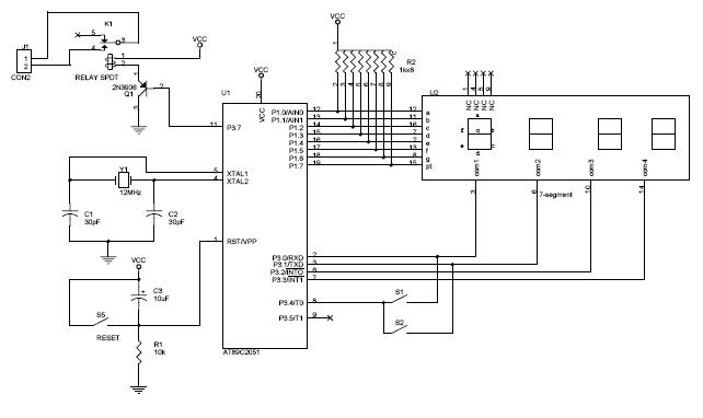
The circuit diagram above illustrates the Clock Controller V1.1. Pins P3.0 to P3.3 are connected to the base of a 4-PNP transistor, specifically the 2N2907, which is used to sink current. The Clock Controller V1.1 circuit is designed to manage...

The circuit can be arranged in a circular format to represent the 12 hours of a clock face, with an additional 12 LEDs positioned in an outer circle to indicate 5-minute intervals within each hour. Four extra LEDs are...
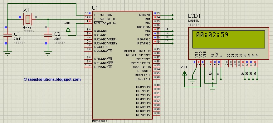
This tutorial on the PIC16F877 microcontroller addresses the question, "How to implement a digital clock using the PIC16F877?" The use of the PIC16 simulator (Proteus) is included. The PIC16F877 microcontroller is a versatile and widely used component in embedded systems,...
This is a programmable clock timer circuit that utilizes individual LEDs to display hours and minutes. Twelve LEDs can be arranged in a circle to represent the twelve hours of a clock face, while an additional twelve LEDs can...
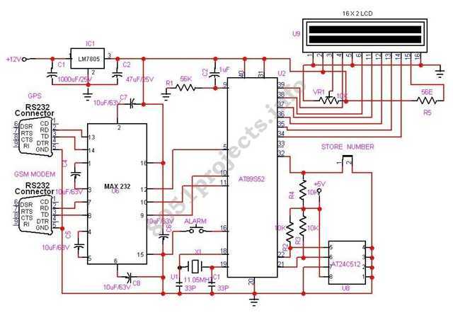
In this project AT89S52 microcontroller is used for interfacing to various hardware peripherals. The current design is an embedded application, which will continuously monitor a moving Vehicle and report the status of the Vehicle on demand. For doing so...
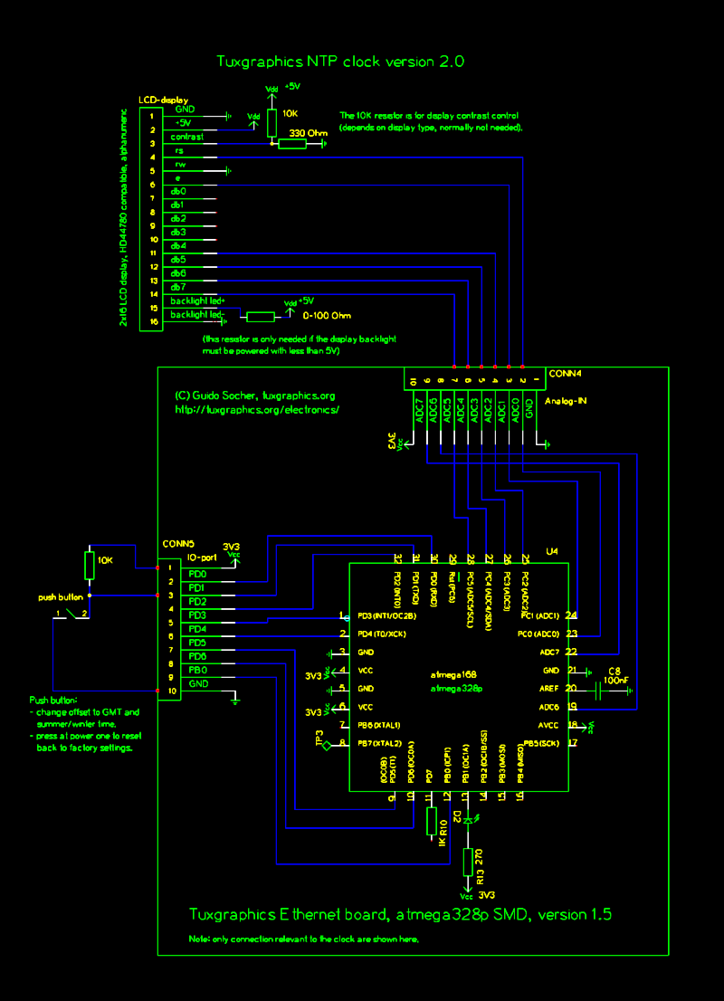
The Network Time Protocol (NTP) has transformed global timekeeping, enabling accurate date and time retrieval from anywhere in the world. NTP is a straightforward UDP-based protocol that can be implemented in microcontrollers. The Tuxgraphics NTP clock has gained popularity...