
pic16f877 based digital clock using lcd display codeproteus simulation
The PIC16F877 microcontroller is a versatile and widely used component in embedded systems, particularly suitable for projects like digital clocks. Implementing a digital clock using this microcontroller involves several key components and steps.
The design typically includes a real-time clock (RTC) module or timer to keep track of the current time. The microcontroller interfaces with the RTC to retrieve time data, which is then processed and displayed. The circuit may also incorporate a 7-segment display for visual representation of the time, as well as buttons for setting the time and adjusting the alarm features.
The schematic would generally include the following essential components:
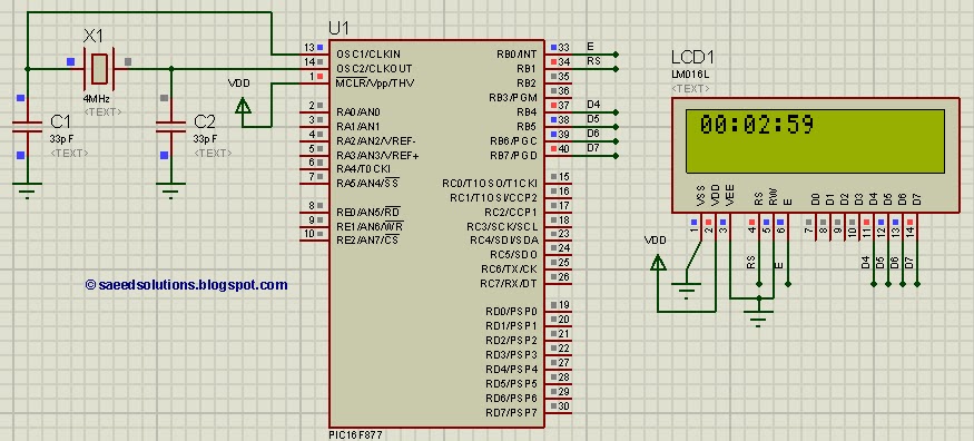
1. **Microcontroller (PIC16F877)**: Acts as the central processing unit, executing the program that controls the clock functions.
2. **Real-Time Clock (RTC) Module**: Often an external component like the DS1307 or DS3231, this module provides accurate timekeeping and communicates with the PIC via I2C protocol.
3. **7-Segment Display**: This display is used to show the hours and minutes. Multiple 7-segment displays may be multiplexed to show the complete time.
4. **Buttons**: Typically, at least two buttons are used for setting the time and toggling between different modes (e.g., time display, alarm setting).
5. **Power Supply**: A stable power source, such as a 5V DC supply, is necessary to power the microcontroller and associated components.
6. **Resistors and Capacitors**: These components are used for current limiting, debouncing switches, and filtering power supply noise.
The programming of the PIC16F877 involves using an integrated development environment (IDE) such as MPLAB X, where the code is written in C or assembly language. The program should handle time increments, display updates, and user input for setting the clock.
In summary, implementing a digital clock with the PIC16F877 microcontroller involves careful selection of components, circuit design, and software programming to ensure accurate timekeeping and user-friendly operation. The use of simulation software like Proteus can aid in visualizing the circuit and debugging the code before physical implementation.This PIC16F877 microcontroller tutorial answers the question, "" How to implement a digital clock using PIC16F877 ? "" Using PIC16 simulator (Proteus) you ca.. 🔗 External reference
Related Circuits
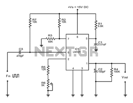
The LM331 is a precision voltage-to-frequency converter developed by National Semiconductors. This integrated circuit (IC) has various applications, including analog-to-digital conversion, long-term integration, voltage-to-frequency conversion, and frequency-to-voltage conversion. Its wide dynamic range and excellent linearity make it suitable for...
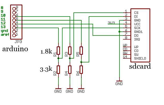
A BASIC preprocessor has been developed using Python, enabling code writing without line numbers and allowing the use of labels. This preprocessor automatically assigns line numbers to the code and converts labels accordingly. An example of its application is...
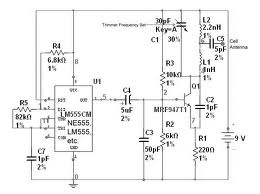
The team is highly interested in the design of a jammer circuit and has begun working on it. However, they are experiencing issues with the circuit, specifically that the signal is not being jammed effectively. The design of a jammer...
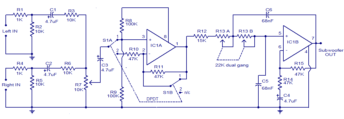
The circuit diagram depicts a simple and effective subwoofer filter designed to operate from a 12V DC supply. This circuit is particularly useful in car subwoofer applications. It functions as a low-pass filter with an adjustable pass frequency ranging...
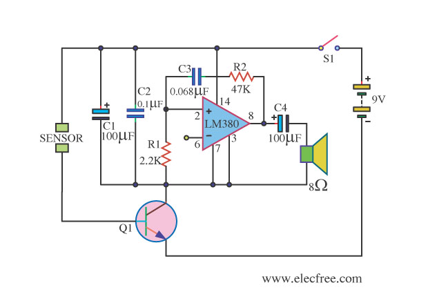
This is a water sensor alarm circuit designed to warn users about water levels. It activates an audible alarm when the sensor comes into contact with water, such as during rainfall. The water sensor alarm circuit functions primarily as a...
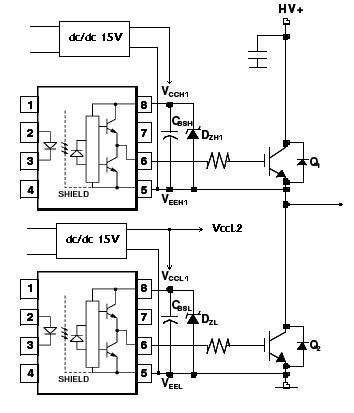
An H-bridge circuit has been developed utilizing four floating gate drivers and four insulated gate bipolar transistors (IGBTs). The attached schematic illustrates one half of the H-bridge configuration. The circuit operates effectively, but there are additional considerations to address. The...
Warning: include(partials/cookie-banner.php): Failed to open stream: Permission denied in /var/www/html/nextgr/view-circuit.php on line 713
Warning: include(): Failed opening 'partials/cookie-banner.php' for inclusion (include_path='.:/usr/share/php') in /var/www/html/nextgr/view-circuit.php on line 713