
12V Analogue Battery Volt Meter

The voltage measurement circuit for a 12V lead-acid battery system is constructed to provide a reliable indication of the battery's state of charge. The design utilizes an analog meter movement calibrated to display voltages within the range of 10-15V, which is typical for lead-acid batteries during their operational lifecycle. The circuit employs a 78L08 voltage regulator, which ensures a stable output voltage while filtering out transient spikes through an RC network composed of a 10-ohm resistor and a 0.1µF capacitor. This filtering is crucial for protecting sensitive components from voltage fluctuations that may occur in solar-powered applications.
A 1 Amp series fuse is included to safeguard the circuit against short circuits, while a Transzorb component provides over-voltage protection, enhancing the robustness of the design. The construction involves using a perforated circuit board, allowing for straightforward assembly and point-to-point wiring. Teflon insulation is employed to prevent short circuits between exposed connections, ensuring safety and reliability in operation.
For alignment and calibration, the circuit is initially tested in parallel with a digital voltmeter to ensure accurate readings. This procedure involves adjusting gain and offset controls to achieve precise measurements across the specified voltage range. The design permits continuous connection to the battery, drawing minimal current, which is advantageous for maintaining long-term monitoring without significant battery drain. The overall configuration is designed with practical considerations for installation in standard electrical enclosures, ensuring that the meter and circuit board are adequately housed and protected from environmental factors.This circuit is used to measure the voltage on a 12V (nominal) lead acid rechargeable battery system. It was specifically designed for use in solar powered systems, but is general enough that it can be used for automotive or other 12V systems.
Lead acid batteries normally spend their working lifetime in the voltage range of 11-15 Volts. This meter circuit was designed to show the voltage range of 10-15V on an analog meter movement, it can be used to show the battery charge state from empty to full. Specifications Measured Volts: 10-15 Volts DC Circuit Current: 9.2mA at 15 Volts DC input Theory The input voltage is filtered from transient voltage spikes via the 10 ohm resistor and the 0.1uF capacitor on the input of the 78L08 regulator. The 1 Amp series fuse and Transzorb protect the circuitry from short circuits and over-voltage conditions.
Construction An approximately 1³x3³ piece of perforated circuit board material was drilled with two holes so that the board could be mounted on the two terminals of the analog meter. The parts were assembled on the perforated board and connected together with point-to-point wiring. Teflon insulation was used over bare wires to make the cross-board connections. The two battery leads were twisted together, then secured to the edge of the circuit board with a loop of wire to prevent movement.
The meter was mounted on a 4³x4³ metal plate that was cut and drilled to fit onto a standard electrical switch box. The box should be deep enough that the meter and accompanying circuit board do not touch the back of the box.
Alignment The circuit should be wired in parallel with a digital Volt meter, both meters should be connected to a stable variable voltage power supply that is capable of operation in the 10-15V DC range. Set the input voltage to 12.5V, set the gain control to midway, and adjust the offset control until the meter reads in the center of its range.
While watching the digital meter, move the input voltage to 12.0V. Observe the analog meter position. Adjust the input voltage to 13.0V and observe the meter position again. If the meter swings more than 1V on the dial, decrease the gain control. If it swings less, increase the control. Repeat this until the meter accurately measures a 1V change. Set the input voltage to 12.5V, adjust the offset control so that the meter shows 12.5V. It will probably be necessary to adjust both controls alternately to get the meter aligned exactly. Observe the meter readings at 10.0V and 15.0V, adjust the controls until it reads the end-point voltage accurately. Use Connect the circuit across a 12V battery and observe the voltages. The meter consumes a small enough amount of current that it can be left connected all of the time for all but the smallest of batteries.
🔗 External reference
Related Circuits
This 4.5-digit digital voltmeter (DVM) circuit is designed around the Maxim ICL7129ACPL analog-to-digital converter (A/D converter) and an LCD driver. It utilizes an ICL8069 CCZR 1.2-V band-gap reference diode for voltage referencing. The switch S2a-b-c allows the selection of...
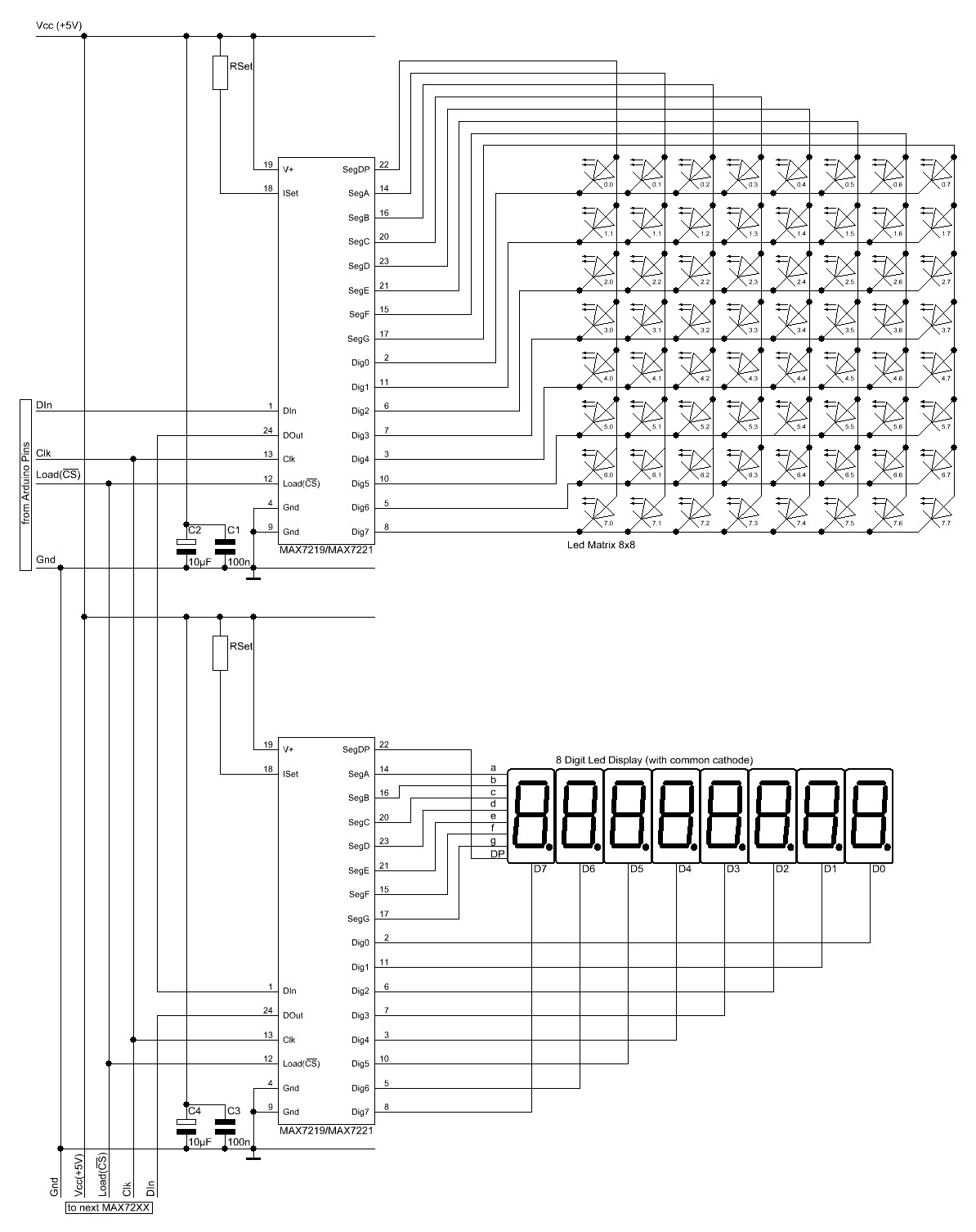
The Arduino website provides comprehensive documentation on connecting LEDs to the Arduino using the MAX7221. A specific set of components is required for this setup. The MAX7221 is a versatile LED driver that enables the control of multiple LEDs through...
S/PDIF is an acronym for Sony /Philips Digital Interface (or Sony /Philips Digital Interconnect Format). The full specification for the S/PDIF interface consists of hardware and software, but only the hardware side will be discussed here - the software...
This 1.5 volt LED flasher runs more than a year on a single 'D' cell and alternately flashes 2 LEDs at about a 1 second rate. The circuit employs a 74HC14 CMOS hex inverter that will operate at very...
R2 must be adjusted to establish the correct finish charge voltage. Flooded and gel batteries are typically charged to 13.8V. For cycling batteries, such as AGM or gel types, battery manufacturers generally recommend a voltage range of 14.5V to...
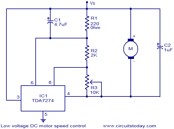
The circuit diagram illustrates a low voltage/low power DC motor speed controller utilizing the TDA 7274 integrated circuit from ST Microelectronics. The TDA 7274 is designed for low voltage and low power applications, featuring an internal voltage reference, a...
Warning: include(partials/cookie-banner.php): Failed to open stream: Permission denied in /var/www/html/nextgr/view-circuit.php on line 713
Warning: include(): Failed opening 'partials/cookie-banner.php' for inclusion (include_path='.:/usr/share/php') in /var/www/html/nextgr/view-circuit.php on line 713