
Accelerometercontrolled LED Bike Helmet

The MAX7221 is a versatile LED driver that enables the control of multiple LEDs through a microcontroller like the Arduino. This IC can drive up to 64 individual LEDs or 8 seven-segment displays with a simple serial interface, making it ideal for projects requiring extensive LED control with minimal GPIO pin usage.
To connect LEDs to the Arduino via the MAX7221, the following components are typically required:
1. **Arduino Board**: Any compatible Arduino board such as the Arduino Uno, Mega, or Nano.
2. **MAX7221 IC**: This chip serves as the LED driver and is responsible for managing the LED outputs.
3. **LEDs**: Depending on the application, various types of LEDs can be used, including standard, RGB, or seven-segment displays.
4. **Resistors**: Current-limiting resistors are necessary to prevent excessive current from damaging the LEDs. The value of the resistors will depend on the specifications of the LEDs being used.
5. **Power Supply**: A suitable power supply is needed to power the Arduino and the MAX7221, ensuring that the voltage levels are appropriate for the components in use.
6. **Breadboard and Jumper Wires**: For prototyping the circuit, a breadboard and jumper wires will facilitate easy connections between the components.
The connection process involves wiring the MAX7221 to the Arduino using the SPI interface, which typically includes connecting the CS (Chip Select), CLK (Clock), and DIN (Data In) pins. The MAX7221 also requires power and ground connections. The Arduino will send commands to the MAX7221 to control the state of each LED, allowing for complex lighting patterns and effects.
In conclusion, utilizing the MAX7221 with an Arduino provides a powerful method for managing multiple LEDs efficiently, enhancing the capabilities of various electronic projects. The documentation on the Arduino website serves as a valuable resource for understanding the setup and programming required to implement this configuration effectively.The Arduino site has thorough documentation on how to connect LEDS to the Arduino via the Max7221. For this, you will need this subset of ingredients.. 🔗 External reference
Related Circuits
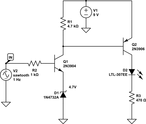
A LED is used to indicate when a DC voltage reaches 5 volts or more. The LED should be fully illuminated at 5 volts and not dim at 4.5 volts or lower. The circuit should be constructed using discrete...
I needed a pulsating light for a certain signaling. Voltage was 230V. So I decided to make a simple circuit, consisted of a LED diode, two capacitors, two resistors, a diac and a diode. Activity of the circuit is...
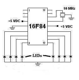
This was my first successful project with a PIC chip. I used a 16F84 with a 10MHz resonator with built-in caps. Click here to view the source code to this project. The code is written in Hi-Tech C. Click...
In this circuit, the 555 timer is utilized in an innovative manner as a voltage-controlled switch. The widely used NE555 can perform effectively in various applications. The 555 timer, a versatile integrated circuit, is commonly employed in timer, delay, pulse...
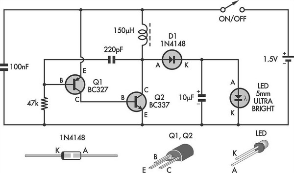
This simple LED torch is powered by a 2-transistor blocking oscillator that increases the voltage from a 1.5V cell. The design utilizes the natural current limiting characteristics of a 150 µH choke to prevent the white LED from being...
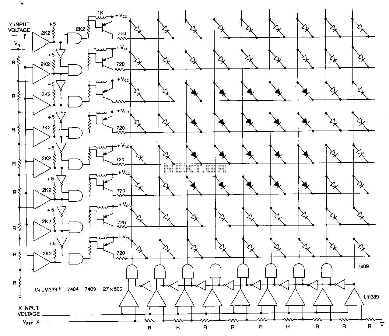
This matrix can display the values of two variables, such as frequency and voltage. The display consists of a graph made from a matrix of LEDs. The LEDs on each axis are color-coded: red indicates out of tolerance, while...