
12v automotive electrical voltage
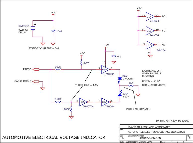
This voltage indicator circuit is designed to provide a simple and efficient means of assessing the voltage levels in an automotive electrical system. The use of two AA or two N cells as a power source ensures long-lasting operation, making it suitable for both professional mechanics and DIY enthusiasts. The circuit's two leads serve distinct purposes: the first lead is connected to the vehicle's chassis ground, establishing a reference point for voltage measurement, while the second lead, equipped with a sharp probe, allows for easy contact with various points in the electrical system.
The functionality of the circuit is straightforward. It operates by comparing the voltage level at the probe tip with the chassis ground. If the voltage detected is approximately +12V, the circuit activates a green LED, providing a clear visual indication that the electrical circuit is functioning correctly. Conversely, if the voltage is close to ground potential, a red LED is illuminated, signaling a potential issue with the circuit. In the case of an open circuit, neither LED will light up, indicating a lack of voltage or a break in the circuit continuity.
The design of this circuit is particularly advantageous due to its low power consumption during standby mode, eliminating the need for an on/off switch. This feature enhances user convenience, as the tool can be left connected without the risk of draining the batteries. The simplicity of the circuit, combined with its effective visual feedback through LED indicators, makes it an invaluable tool for automotive troubleshooting, allowing for quick and reliable assessments of electrical systems.When troubleshooting the 12v electrical system of an automobile, its nice to possess an easy voltage indicator tool rather than a voltmeter. This electronic circuit, is powered by 2 AA or perhaps 2 N cells, which can offer enough energy for years of service.
The circuit has solely two leads. One lead connects to the chassis ground of the automotiv e. The second lead will be sharp tip probe. The circuit can indicate if an automotive electrical circuit has zero volts or 12 volts present. If the voltage is close to +12v, a inexperienced LED will activate. If the voltage is close to chassis ground a red LED will activate. If the circuit is open, neither light will light. The circuit attracts so few current in the open standby mode that no on/off switch is needed. 🔗 External reference
Related Circuits
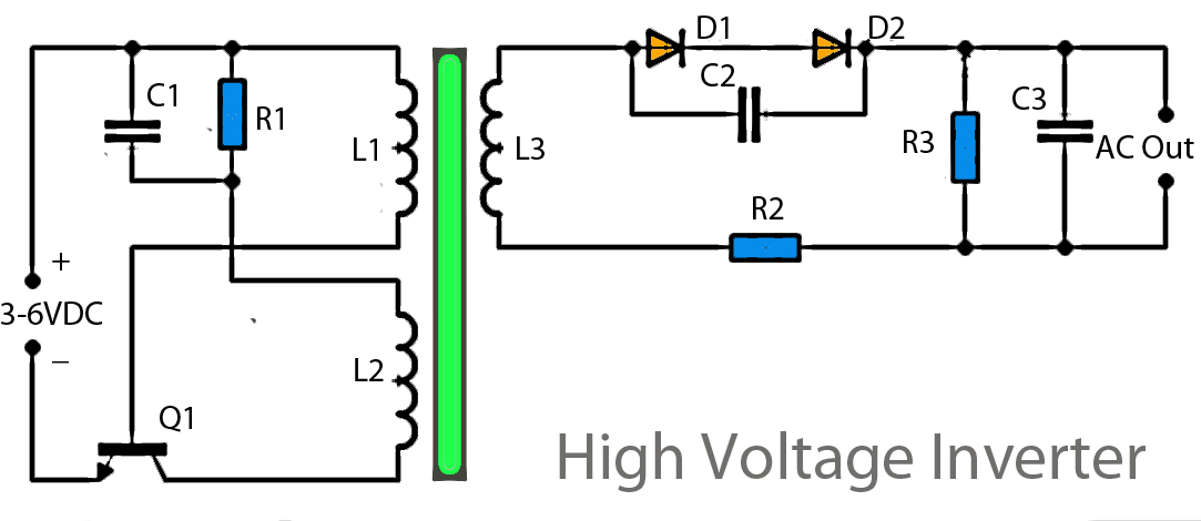
This inverter circuit operates using a transistor and transformer, along with other components, to elevate the voltage. The input supply voltage ranges from 3V to 6V DC, which is then converted to a high voltage AC output. However, the...
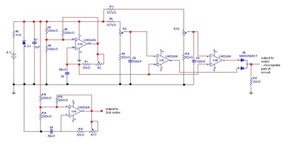
The goal is to control the speed of a 6-volt brush DC motor using a linear potentiometer and to create an oscillating speed effect, with the oscillation frequency also adjustable via a linear potentiometer. The desired complete cycle peak-to-peak...
At a T connection, the connections are clear, but at a cross, the connections are not clear, especially if there are no junction dots elsewhere in the schematic. It appears that the bottom of the I and the right...
A dimmer is relatively uncommon in a caravan or on a boat. This document outlines how to create one, allowing for mood adjustment in these environments. A dimmer switch is an essential component for controlling lighting levels in various settings,...
If the offset value exceeds 5mV, adjust this value by experimenting with resistors, starting with 220K, connected from test point Z (the junction of R22 and R23) to +V if there is a negative voltage, or to -V if...
The challenge is to control the speed of the motor. One approach is to use a plane, radio, and speed control integrated with the motor, but this is not ideal. Alternatively, mounting the motor on a bench and directly...
Warning: include(partials/cookie-banner.php): Failed to open stream: Permission denied in /var/www/html/nextgr/view-circuit.php on line 713
Warning: include(): Failed opening 'partials/cookie-banner.php' for inclusion (include_path='.:/usr/share/php') in /var/www/html/nextgr/view-circuit.php on line 713