
12V Dimmer
A dimmer switch is an essential component for controlling lighting levels in various settings, including caravans and boats, where space and energy efficiency are paramount. The design of a dimmer circuit typically involves a combination of resistors, capacitors, and a control mechanism, such as a potentiometer or a microcontroller, to modulate the voltage supplied to the light source.
For a basic dimmer circuit, a TRIAC (Triode for Alternating Current) can be employed to manage the power delivered to the light fixture. The TRIAC is triggered by a phase control technique, which adjusts the point in the AC cycle at which the TRIAC is activated. This is achieved through a simple RC (resistor-capacitor) network connected to the gate of the TRIAC. The values of the resistor and capacitor dictate the delay before the TRIAC turns on during each AC cycle, effectively controlling the brightness of the light.
To implement this circuit, the following components are required:
1. A TRIAC rated for the expected load current and voltage.
2. A diac, which helps in triggering the TRIAC at a specific voltage threshold.
3. A potentiometer to allow user adjustment of the dimming level.
4. Resistors and capacitors to form the timing circuit.
The circuit should be designed with safety in mind, particularly in a marine or mobile environment. Proper insulation and waterproofing measures must be taken to protect the components from moisture and vibrations. Additionally, a fuse should be included to safeguard against overcurrent conditions, and the circuit should be housed in a secure enclosure to prevent accidental contact.
Once assembled, this dimming circuit can significantly enhance the ambiance of a caravan or boat, allowing users to create the desired lighting conditions for various activities, whether it be relaxing in the evening or navigating during the night.A dimmer is quite unusual in a caravan or on a boat. Here we describe how you can make one. So if you would like to be able to adjust the mood when you re.. 🔗 External reference
Related Circuits

This design is likely to generate significant radio frequency interference (RFI) without the incorporation of a choke. The house wiring serves to limit the rate of change of current (di/dt). It is a cost-effective design that demonstrates hysteresis at...
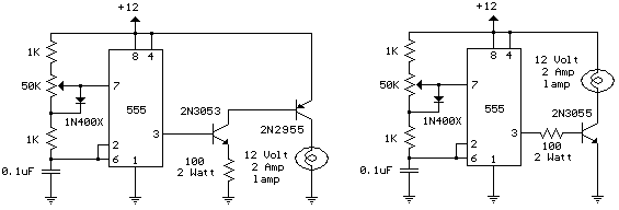
The schematic diagram illustrates a 12 Volt Car Lamp Dimmer Circuit Design utilizing a 555 Timer. This circuit can be employed to dim a standard 25-watt lamp. The 12 Volt Car Lamp Dimmer Circuit utilizes a 555 Timer in astable...
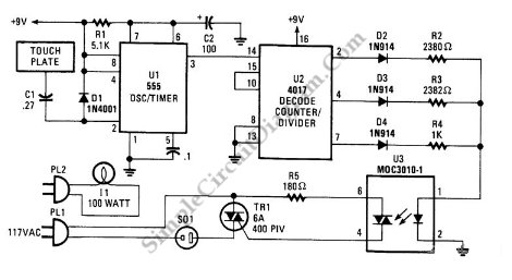
This is a three-mode lamp dimmer circuit with touch control. This circuit can be used to control a lamp in three operation modes: dim, off, and bright. A NE555 timer is utilized in the design. The three-mode lamp dimmer circuit...
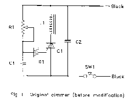
The circuit (before flameout) worked like this: device Q1 is a triac, which is a power-switching device. When triggered, it switches to a fully conducting state and stays that way until the current passing through it goes to zero....
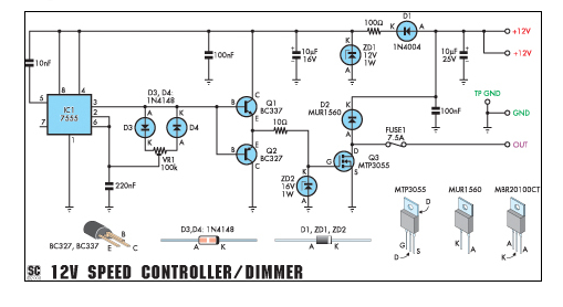
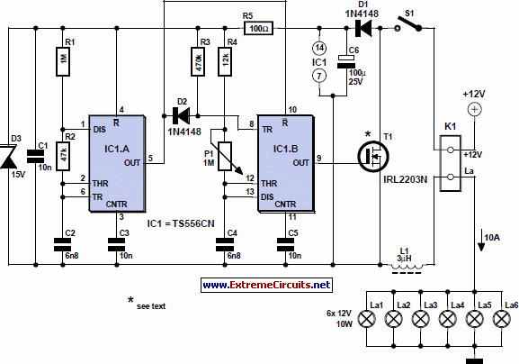
This circuit can function as a speed controller for a 12V motor with a continuous rating of up to 5A or as a dimmer for a 12V halogen or standard incandescent light. The circuit utilizes a pulse-width modulation (PWM) technique...

This inverter circuit is designed to power electric razors, stroboscopes, flash tubes, and small fluorescent lamps using a 12-volt car battery. Unlike typical feedback oscillator inverters, this design features a separate oscillator from the output stage, allowing for easy...