
12v Battery Charger Circuit with Auto Cut off
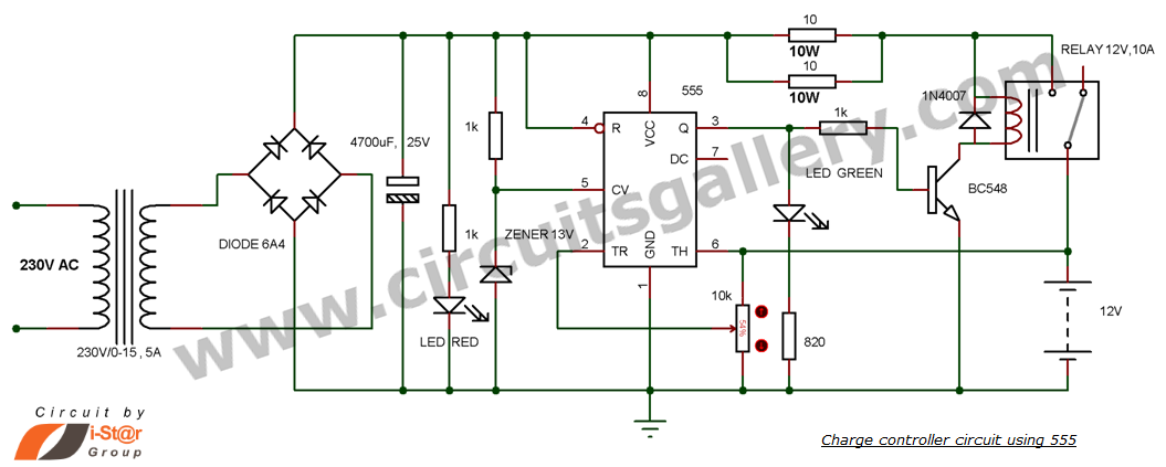
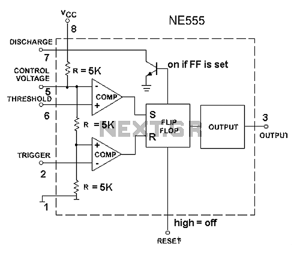
This DIY charge controller schematic employs a 555 timer IC configured in a comparator mode to manage the charging of a 12-volt lead-acid battery. The circuit operates by monitoring the battery voltage and controlling the charging process based on predefined voltage thresholds. The 555 timer has two comparators: one for the upper threshold (13.8 volts) and one for the lower threshold (12 volts).
When the battery voltage is below 12 volts, the output of the lower comparator remains low, allowing the flip-flop to reset. This condition activates the transistor, which in turn energizes the relay, connecting the charger to the battery. As the battery charges and the voltage rises, once it reaches 13.8 volts, the output of the upper comparator transitions high, setting the flip-flop. This action turns off the transistor, deactivating the relay and disconnecting the charger from the battery, thus preventing overcharging.
The variable resistor in the circuit allows for fine-tuning of the charging voltage, accommodating different battery chemistries and conditions. This flexibility is crucial for optimizing battery life and performance. The circuit's design also emphasizes safety and reliability, ensuring that the battery is charged efficiently while safeguarding against damage from overvoltage.
For practical implementation, it is essential to refer to the pinout of the 555 timer to ensure correct connections. Additionally, understanding the operation of the relay is critical, as it serves as the switch that controls the power to the battery. Resources that demonstrate relay functionality can provide valuable insights into this aspect of the circuit.
Overall, this simple charge controller schematic offers an effective solution for managing battery charging in a DIY setting, combining ease of use with essential protective features.This is a simple DIY charge controller schematic posted in response to a request by one of our readerson our facebook page. The main component of this auto battery charger circuit is a 555 timer which compares the voltage in the battery.
It turns ON the charger if the battery voltage is below the variable preset voltage (12 volt chosen here) and turns OFF the charger if the voltage reaches 13. 8 volt. The battery charging voltage of the charger can be varied by adjusting the variable resistor. To understand the working of this12 volt battery charge controllercircuit you must have an idea of the internal diagram of 555. You can refer the pin out section at the bottom. You must also check charge controller using LM324 IC where you can find video demonstration too. If the battery voltage is greater than 13. 8V, comparator output goes high and flip flop will be set. This turns OFF the transistor and the relay. For understanding relay working see How to connect relay: Relays working with animation If the battery voltage is below the preset voltage (set by us), lower comparator will reset the flip flop.
This turns ON the transistor and the relay will switch to charge the battery. 🔗 External reference
Related Circuits
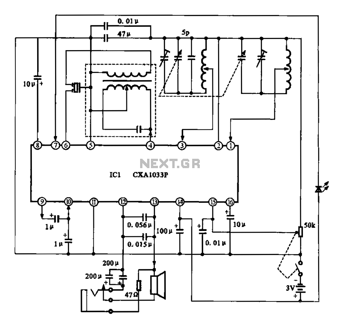
The AM radio features a monolithic circuit design. The broadcast signal is received by an antenna, which feeds into a high-efficiency mixer. The output from the intermediate frequency (IF) transformer undergoes filtering before being sent to the IC1. The...
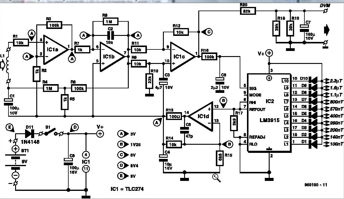
Some experts believe that static magnetic fields (SMFs) may affect the physical well-being of individuals. If one subscribes to this viewpoint, the magnetic-field meter described here will aid in locating sources of SMFs and assessing their strength. These results...
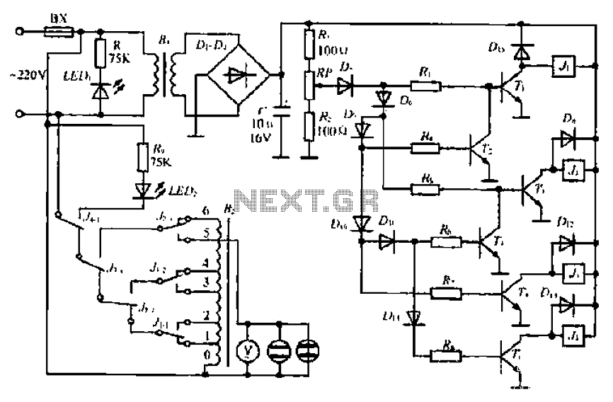
A step-down transformer converts AC 220V to a lower voltage. A diode bridge rectifier and filter capacitor provide a direct current (DC) output, which fluctuates with variations in the grid voltage. A resistive voltage divider is used for sampling....
The 555 timer circuit, regardless of the manufacturer, has a consistent internal structure and performance. Various manufacturers produce different models of the 555 timer, including MC555, CA555, XR555, LM555, as well as domestic models like SL555, FX555, and 5G1555....
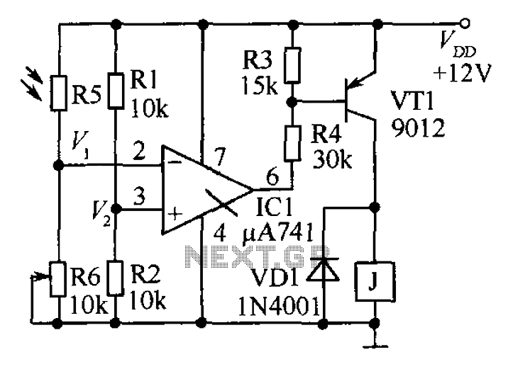
The circuit functions as a precision bright light control circuit, operating independently of power supply voltage and ambient temperature. Resistors R1, R2, R6, and the photosensitive resistor R5 form a two-arm Wheatstone bridge. The precision bright light control circuit utilizes...
In the circuit, a quad voltage comparator (LM339) functions as a simple bar graph meter to display the charge condition of a 12-volt lead-acid battery. A 5-volt reference voltage is applied to each of the positive inputs of the...