
led 12 volt lead acid battery meter
The circuit utilizes the LM339, a quad comparator, which allows for the monitoring of battery voltage levels with multiple output indicators. The 12-volt lead-acid battery is monitored through a voltage divider, which scales down the battery voltage to a range suitable for comparison with the fixed 5-volt reference. This is achieved by using resistors in a series configuration, where the voltage at each tap point corresponds to a specific battery voltage level.
The output from each comparator is connected to individual Light Emitting Diodes (LEDs). When the voltage at the negative input exceeds the 5-volt reference, the comparator output goes high, turning on the corresponding LED. This configuration allows for a visual representation of the battery's state of charge, where each illuminated LED indicates a specific voltage threshold.
The design ensures that the circuit can effectively monitor the battery's charge status in real-time, providing immediate feedback on the battery's health. The use of the LM339 comparator is advantageous due to its low power consumption and ability to operate over a wide voltage range, making it suitable for battery management applications. Proper selection of resistor values in the voltage divider is crucial to ensure accurate voltage scaling and threshold detection, thereby enhancing the reliability of the bar graph meter display.In the circuit, a quad voltage comparator (LM339) is used as a simple bar graph meter to indicate the charge condition of a 12 volt, lead acid battery. A 5 volt reference voltage is connected to each of the (+) inputs of the four comparators and the (-) inputs are connected to successive points along a voltage divider.
The LEDs will illuminate when the voltage at the negative (-) input exceeds the reference voltage.. 🔗 External reference
Related Circuits
One cannot expect high performance from a basic detector-based meter. Its sensitivity is merely sufficient to provide a fundamental understanding of the power output that the transmitter can achieve. The detector-based meter operates on a straightforward principle where it measures...
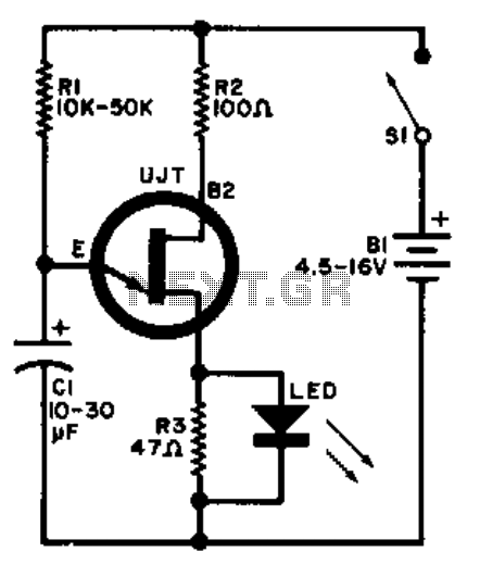
A relaxation oscillator is employed to flash an LED in the base circuit. The capacitor C1 is charged slowly through resistor R1 by the power source, and then it is discharged periodically through resistor R3 and the LED by...
This high voltage converter circuit operates from a 30-volt power supply and can output a voltage ranging from 0 to 3 kV in version 1 or from 0 to 10 kV in version 2. The high voltage converter circuit is...

Here is a design for a temporary lamp circuit that is very helpful in emergency situations or in any application where there is limited time to turn off the lamp. Simply press the push button to perform a quick...
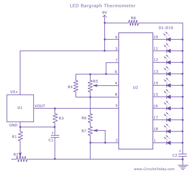
An LED thermometer that can function as a temperature sensor or temperature measurement circuit, utilizing the LM34 for Fahrenheit display or the LM35 for degree Celsius display. The LED thermometer circuit is designed to provide accurate temperature readings using either...
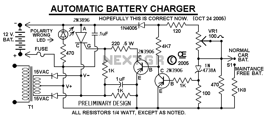
This Charger Can't be used as a Power Supply, Without having a battery in place. The Battery MUST be Connected to get power out. Note: This Charger Features a Reverse polarity Indicator. Instructions: Before plugging this charger into the...