
An automatic voltage regulator circuit
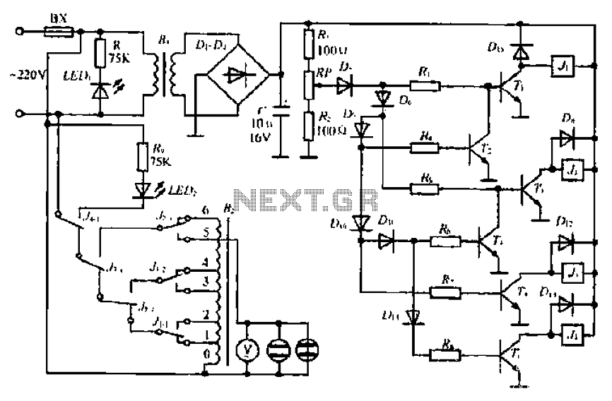
The circuit begins with an AC 220V input, which is transformed down to a lower voltage using a step-down transformer. The output from the transformer is then fed into a diode bridge rectifier, which consists of four diodes arranged in a bridge configuration. This setup converts the alternating current (AC) into pulsating direct current (DC). A smoothing capacitor is connected in parallel to the output of the rectifier to filter the pulsating DC, providing a more stable DC voltage.
To monitor and regulate this output voltage, a resistive voltage divider is implemented. This divider allows for sampling of the output voltage, providing feedback to the control system. As the grid voltage fluctuates, the circuit is designed to respond accordingly. For instance, at a grid voltage of 160V, all diodes in the circuit become conductive, facilitating maximum voltage transfer to the regulator.
As the grid voltage increases to 175V, a switching mechanism is triggered, altering the configuration of the circuit to accommodate the higher voltage. This is crucial for maintaining system stability and preventing damage to components. When the voltage reaches 190V, additional diodes and control elements engage, further managing the output to ensure it remains within safe operational limits.
When the voltage rises to 205V, specific diodes become active, grounding certain bases to cut off excess voltage and prevent over-voltage conditions. The system is designed to handle input voltage variations up to 235V, at which point additional protective measures are activated. If the voltage exceeds 250V, the circuit engages an overvoltage indication system, alerting to the potential risk of damage.
In summary, this circuit employs a combination of a step-down transformer, diode bridge rectifier, filtering capacitors, and a series of protective components to manage AC to DC conversion, voltage regulation, and over-voltage protection. This ensures reliable operation in varying grid conditions while safeguarding the integrity of the system. By AC 220V step-down transformer Lu. Former -q diode bridge rectifier, filter capacitor C becomes a straight stream. The DC voltage varies with fluctuations in the grid. R.. Ri and RP divider consisting of changes BU galvanic JE sampling, RP center sampling voltage BU liters diode dish, D., D, D ,. , Dii Du sequentially turned on; when the grid voltage is 160V, all diodes cut J Bu, I- J4 full release, with electrical voltage connected to the regulator, the maximum boost end ] position; grid electricity to destroy 175V fixed sometimes, health hurricane, Tj guide sister, 1 suction units switch to 2 position; voltage of 190V/death the right time,, L is turned on, Jl suction units, meaning turn switch to 3 position; electric board when 205V, D7, D, j 1 conduction base is grounded Tz a cutoff .Jl release put pull, received 44 : voltage is 220V.
Dm. Ding 5 cut mound, on,/liht Taiwan, received 5. When the input voltage and the output m the same: if the voltage continues to rise around the time t 235V, then Dn, L lead framed, T3 cut ll, on release. Suction units, received a 6 for the buck lose fi {: if the electric voltage is increased to ridicule 250v, this time D..
T is turned. Friends, cutting eight auxiliary electric Shu, converted to an overvoltage indication I, FD, lit., Q is the only stable voltage input instructions.
Related Circuits
This circuit utilizes two CMOS ICs: a 4011 quad 2-input NAND gate and a 4020 14-stage ripple binary counter. Upon powering on, resistors R2 and capacitor C2 generate a brief reset pulse, ensuring that the output pin Q1 of...
This circuit represents a low-cost printer sharing device that was developed some time ago. The product was encapsulated in epoxy with a black dye and had a limited commercial release. The output impedance of this circuit is high, with...
This sound effects circuit is designed to function as a signal distorter. When utilized with an electric guitar, it enables the creation of unique sound effects. The sound effects circuit operates by manipulating the input audio signal from the electric...
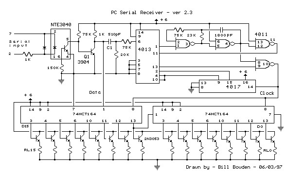
This circuit requires physical connections to be made to the computer's serial port (COM1 or COM2). It is generally considered difficult to cause harm to oneself or the computer through improper connections to this port; however, there is no...
Designs for audio amplifiers with DC coupling to the load are not frequently seen today, despite offering distinct advantages. Audio amplifiers that employ DC coupling to the load provide several benefits that can enhance performance in specific applications. In traditional...
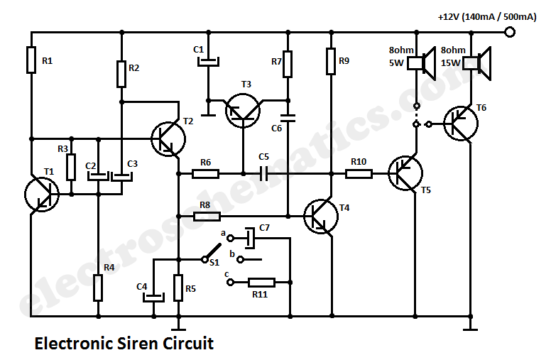
This circuit generates a tone that resembles a siren. The generator section consists of a combination of PNP and NPN transistors that form a free-running multivibrator. If capacitor C2 were connected to the positive line of the power supply,...