
12V Battery to 220V Power Inverter charge controller
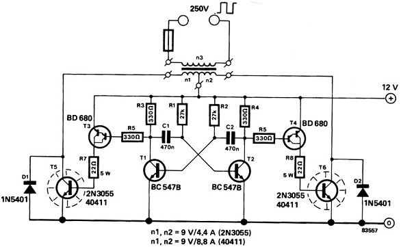
The 12V power inverter circuit typically consists of several key components that work together to achieve the conversion from DC to AC. At its core, the inverter employs a switching mechanism, often utilizing transistors or MOSFETs, to rapidly switch the DC voltage on and off. This switching creates a square wave output, which can then be transformed into a sine wave using additional filtering and modulation techniques.
The circuit begins with a DC power source, commonly a 12V battery. This voltage is fed into an oscillator circuit, which generates a high-frequency signal. The oscillator can be implemented using a 555 timer IC or a microcontroller, depending on the desired complexity and features of the inverter.
Next, the output from the oscillator drives the gates of the transistors or MOSFETs. These components act as switches, turning on and off in response to the oscillator's signal. The switching creates a pulsed output, which is then passed through a transformer. The transformer serves two primary functions: it steps up the voltage to the desired AC level (typically 120V or 230V, depending on the application) and provides electrical isolation between the input and output.
After the transformer, the output may still exhibit a square wave form. To convert this square wave into a more usable sine wave, additional filtering components, such as capacitors and inductors, are employed. These components smooth out the output waveform, reducing harmonic distortion and improving the quality of the AC signal.
Finally, the output can be connected to standard AC loads, enabling the use of household appliances and other devices that require AC power. Safety features, such as fuses or circuit breakers, may also be incorporated into the design to protect against overloads and short circuits, ensuring reliable operation of the inverter.A power inverter converts DC power or direct current to standard AC power or alternating current. The following schematic shows a 12V power inverter Circuit Diagram. 🔗 External reference
Related Circuits
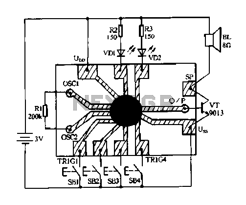
Constantly changing light and sound analog controller circuit 04 The circuit designated as the "Constantly Changing Light and Sound Analog Controller Circuit 04" is designed to modulate both light and sound outputs in a dynamic manner. This type of...
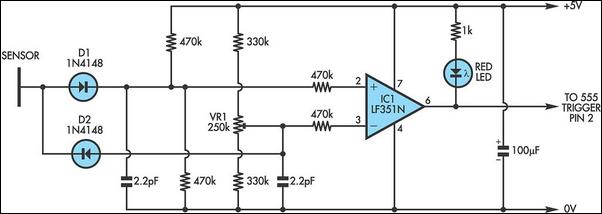
It is well known that simple everyday activities, such as walking on a carpet or moving in a chair, can lead to the accumulation of static charge in the body, sometimes reaching thousands of volts. This circuit is designed...
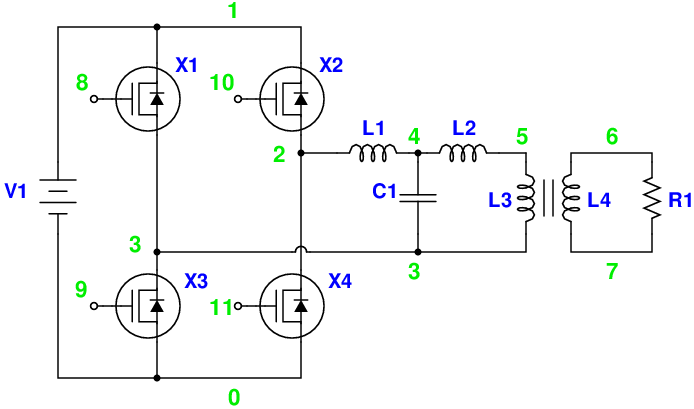
Magic Sinewave Analysis using SPICE and a Simple Inverter Circuit. This document discusses the analysis of a sinewave signal generated by a simple inverter circuit using SPICE simulation software. The inverter circuit is designed to convert a DC input voltage...
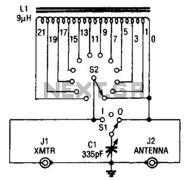
This antenna tuner is designed for low-power transmitters or shortwave receivers with a maximum power output of 5 watts. The switch S2 is used to select the inductance, while S1 connects a 365-pF capacitor either to the transmitter or...
The TDA2005 integrated circuit (IC) features a high output power of 10W per channel (stereo) at a load of 2 ohms with a distortion of 10%, and 20W in bridge mode at a load of 4 ohms with a...
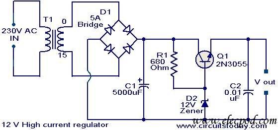
This voltage regulator circuit can deliver up to 3A at a 12V output voltage. The circuit is suitable for applications where a current exceeding 3A is required. Integrated circuit (IC) regulators with such high current ratings are difficult to...
Warning: include(partials/cookie-banner.php): Failed to open stream: Permission denied in /var/www/html/nextgr/view-circuit.php on line 713
Warning: include(): Failed opening 'partials/cookie-banner.php' for inclusion (include_path='.:/usr/share/php') in /var/www/html/nextgr/view-circuit.php on line 713