
12V Car Battery Charger
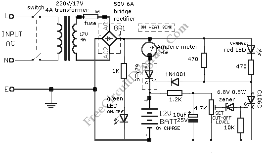
The 12V car battery charger circuit is an essential tool for maintaining the health and longevity of car batteries. The design incorporates a closed-loop control mechanism that continuously monitors the voltage and current flowing into the battery. This ensures that the battery receives the optimal charging current until it reaches full capacity. The circuit typically includes components such as a transformer, rectifier, voltage regulator, and various passive components to stabilize the voltage and current.
The transformer is crucial for stepping down the AC voltage from the mains to a suitable level for charging the 12V battery. The rectifier converts the AC output of the transformer into DC, which is necessary for charging the battery. A voltage regulator may be included to maintain a steady output voltage, preventing overcharging and ensuring the battery is charged efficiently.
The inclusion of a red LED indicator serves as a visual cue for the user, signaling when the charging process is complete. This feature not only enhances user experience but also protects the battery from potential damage due to overcharging.
When constructing the circuit, it is vital to ensure that all connections are secure and that the appropriate gauge of wire is used, particularly for connections involving high current. Using wires with a larger cross-sectional area helps minimize resistance, thereby reducing heat generation and potential voltage drops.
In summary, this 12V car battery charger circuit is designed with safety and efficiency in mind, making it a reliable solution for maintaining car batteries. Proper assembly and attention to detail during construction will ensure optimal performance and longevity of both the charger and the battery.This is 12V Car Battery Charger simple circuit. This circuit is designed to solve some problems that occurs in most car battery chargers. The problem that occur in most car battery chargers is when the charger is not turned off, the battery will overcharge, the plate of the charger will destroyed and the electrolyte of the charger will lost becau se of evaporation. This circuit will monitor the charge condition of the battery by using a closed loop control circuit. A high charge current is applied until the battery is completely charged. Here is the schematic diagram of the circuit: The red LED will turn on, when charging is complete and charging circuit will deactivated.
This circuit used only for 12 V battery. When wiring up the circuit, Certain emphasis should be taken. They are hose supplying current to the battery being charged and the connections of the transformer to the circuit board. To prevent heat build-up and voltage-drop when current flows through the circuit, the connections of the transformer to the circuit board should be made with cables having a large cross-sectional area.
[Source: Sam Electronic Circuit] We aim to transmit more information by carrying articles. Please send us an E-mail to wanghuali@hqew. net within 15 days if we are involved in the problems of article content, copyright or other problems. We will delete it soon. 🔗 External reference
Related Circuits
A straightforward method for charging a battery using a higher voltage source is illustrated in the accompanying circuit diagram. The circuit requires only one resistor to establish the desired charging current, which can be determined by dividing the voltage...
If you use different batteries with actual capacity, with different self-discharge rate of batteries from different manufacturers, you will perhaps throw further described charger. Because each cell can be discharged separately recharge, can be charged with varying articles carrying...
A close friend is interested in a dry cell lead-acid battery charger circuit designed for a 12V, 7.5Ah battery. The proposed model is simple and economical. The recommendation is to build this circuit using the highly popular LM317K integrated...
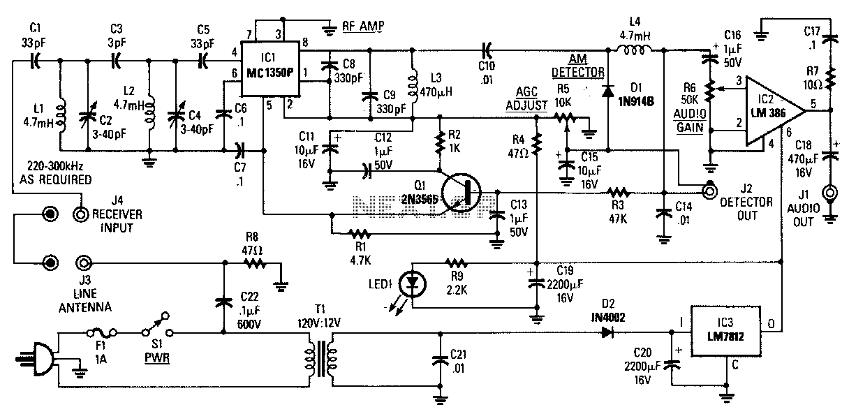
The AM Tuned Radio Frequency (TRF) receiver has a sensitivity of approximately 1 mV at the input for an audio output of 1/2 W. Capacitor C22 couples audio signals from the power line to the PC board and must...
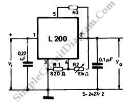
This is a programmable current and voltage regulator circuit. It consists of a voltage regulator with external current limitation. The variable resistor R2 is... The programmable current and voltage regulator circuit is designed to provide precise control over output voltage...
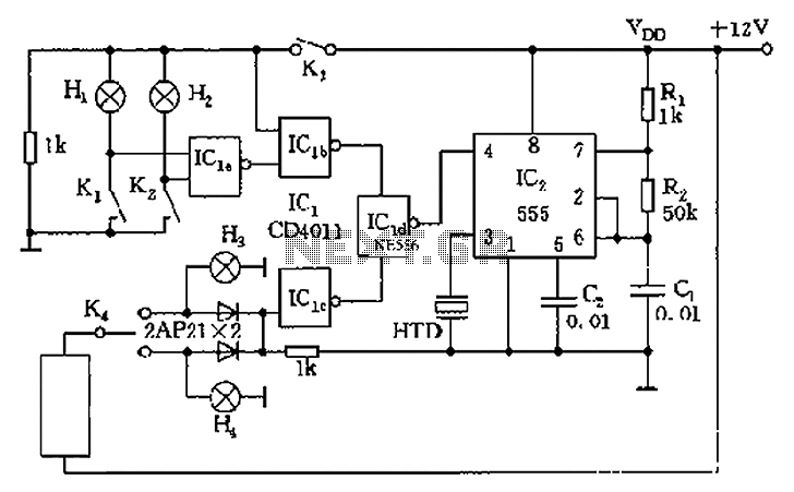
The circuit presented is a 555 timer-based alarm system for vehicles, which primarily consists of a 555 timer and a quad 2-input NAND gate configuration. It is designed to produce a long beep sound when oil pressure is low...
Warning: include(partials/cookie-banner.php): Failed to open stream: Permission denied in /var/www/html/nextgr/view-circuit.php on line 713
Warning: include(): Failed opening 'partials/cookie-banner.php' for inclusion (include_path='.:/usr/share/php') in /var/www/html/nextgr/view-circuit.php on line 713