
555 car alarm circuit diagram

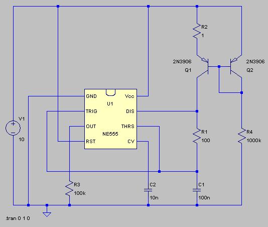
The circuit utilizes a 555 timer in astable mode to generate audible alerts based on specific vehicle conditions. The timer is configured to produce a continuous tone when triggered by low oil pressure and low brake pressure conditions. This is achieved by connecting sensors that detect these conditions to the input pins of the 555 timer. When either sensor detects a fault, it sends a signal to the timer, causing it to activate the alarm.
The quad 2-input NAND gate is employed to provide logical conditions for the circuit. It ensures that the alarm is only triggered when both conditions (low oil pressure and low brake pressure) are met. The outputs from the sensors are fed into the NAND gates, which process the signals and determine if the alarm should sound. The use of NAND gates allows for flexibility in the circuit design, enabling additional features or conditions to be added in the future.
For the steering alert function, a separate circuit can be integrated that monitors the steering position. When the steering wheel is turned, this circuit activates the 555 timer again, but in a different mode, producing an intermittent beep to remind the driver to deactivate the turn signal. This feature enhances driver awareness and promotes safe driving practices.
Overall, this vehicle alarm circuit is a practical application of the 555 timer and logic gates, providing essential alerts to enhance vehicle safety and driver awareness. As shown is 555 more cars with alarm circuit, mainly consists of a 555 and a quad 2-input NAND gate circuit. At the time of low oil pressure and brake pressure is too low, the police will issue a long beep sound; when the car steering, Intermittent sound to alert the driver to turn off the turn signal.
Related Circuits
The typical BPM range for music is between 40 and 240 BPM, corresponding to periods of 1500 ms and 200 ms, respectively. A BPM of 120 equates to a period of 500 ms. The circuit requires a resistor R4...
This circuit warns the user against fire accidents. It relies on the smoke that is produced in the event of a fire. When this smoke passes between a bulb and an LDR, the amount of light falling on the...
The regenerative effect of a 4-quadrant inverter necessitates power dissipation in some form. In large industrial drives, this power is typically re-inverted back onto the national grid. However, for smaller applications, implementing a braking circuit is advisable. For low-power...
The switching circuit consists of a buck rectifier circuit, a bistable trigger circuit, and a thyristor control circuit, enabling remote control for electrical equipment to be turned on or off. The buck rectifier circuit supplies the controller with a...
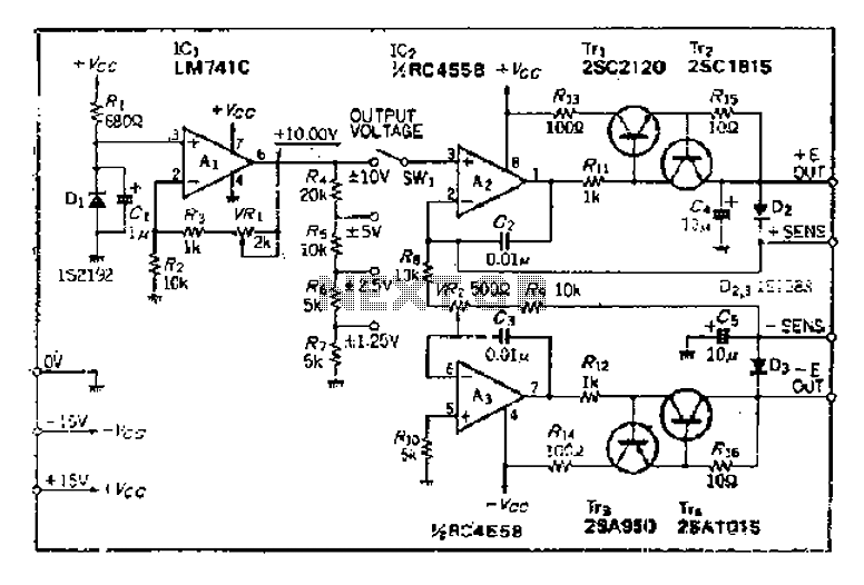
The maximum input voltage is 10V. An operational amplifier (op-amp) is used to provide a reference voltage of 10V, with its stability primarily determined by the characteristics of a temperature-compensated Zener diode (IS2192). The Zener voltage (Vz) can be...

Instructions for creating a Clap-Clap On/Clap-Clap Off switch circuit. This guide provides the necessary information for constructing a clap-activated switch. The Clap-Clap switch circuit is an innovative design that utilizes sound activation to control electronic devices. The primary components of...