
inverter circuit diagram
The described circuit represents a sophisticated approach to inverter design, effectively managing power conversion while ensuring reliability and protection against common failure modes. The use of the SG3524 as a control unit integrates several essential functions into a single component, streamlining the control architecture. The parallel configuration of switches enhances the current handling capability, thereby improving overall efficiency. The IR2110 driver IC plays a pivotal role in managing the switching of the MOSFETs, providing robust protection mechanisms that enhance the system's resilience. The incorporation of undervoltage protection further safeguards the battery and maintains system integrity. Overall, the design exemplifies a comprehensive solution for efficient DC to AC conversion with enhanced safety features.Double-ended working core square wave inverter transformer area product formulaBm is the maximum magnetic flux. Transformer primary side of the switch S1 and S2 in parallel with IRF32055 only reason why parallel, mainly because access to the load in the inverter, the transformer primary current is relatively large, parallel to shunt, which can effectively
reduce the switch power, and will not cause damage. PWM control circuit chip SG3524, is a voltage type switching power supply integrated controller, with output current limit, switching frequency is adjustable, error amplifier, PWM comparator and turn-off circuit, which produces a square wave PWM peripheral circuits required very simple. When the pin 11 and pin 14 parallel, the output pulse from 0 to 95% duty cycle, pulse frequency of the oscillator frequency is equal to 1 / 2.
When the pin 10 (off stump) plus high, can achieve the blockade of the output pulse, and the external circuit properly connected, you can achieve under-voltage, over-current protection. Using SG3524 regulating the internal op amp that comes with the drive waveform of the output duty cycle D, the 50%, and then reverse after CD4011, got on the tube of the drive waveform of D <50%, this can ensure that the two groups switch drive, have a common dead time.
Shown in Figure 3, DC / AC conversion using single-phase output, the form of full-bridge inverter, power inverter for the reduced volume, lower cost, using the frequency out put LC filter. Posed by the four IRF740 bridge inverter circuit, IRF740 maximum voltage 400V, current of 10A, power 125W, using half-bridge driver IR2110 provides driving signal, the input waveform provided by the SG3524, the same way adjustable driver output waveforms of the SG3524 of D <50%, driven by square wave inverter to ensure a common dead time.
IR2110 is a high-power IR company dedicated driver IC MOSFET and IGBT, MOSFET and IGBT to achieve the best driver, but also with rapid complete protection, so it can improve the reliability of the control system to reduce the complexity of the circuit level. IR2110 internal structure and working principle diagram shown in Figure 4. HIN and LIN as the figure in the same bridge inverter bridge arm the next two power MOS drive pulse signal input.
SD for the protection of signal input, when the pin high, then, IR2110 output signal all been blocked, the corresponding constant for the low output; and when connected to the pin low, IR2110 output signal to follow the HIN and LIN and changes in the actual circuit, the termination of the user`s protection circuit output. HO and LO are two output drive signal to drive the same leg of the MOSFET. IR2110 bootstrap capacitor selection is not good, likely to cause damage or chip does not work. Between VB and VS bootstrap capacitor capacitance. Bootstrap capacitor voltage reaches 8. 3V or more, to be able to work, or the use of small-capacity capacitor to increase the charging voltage, either directly in the VB and VS 10 ~ 20V provided between the isolated power supply, the circuit uses a bootstrap capacitor 1 F.
In order to reduce the output harmonics, inverter DC / AC part of the generally used bipolar modulation, the inverter bridge of the pipe is high frequency of complementary and off. Undervoltage protection circuit shown in Figure 5, it monitors the battery voltage condition, if the battery voltage is lower than the default 10.
8V, protection circuit to work, so that the controller SG3524 off stump out of 10 feet high, and stop driving signal output. Figure 5, the forward op amp input voltage from voltage divider R1 and R3 are, while the negative input voltage from the regulator clamped at +7.
5 V, when the battery`s voltage drop exceeds a predetermined value, the operational amplifier to work, the output jump is negative, LED lights, while three tubes V cut-off, the SG3524`s SD-ended output high, blocking the output drive signals 🔗 External reference
Related Circuits
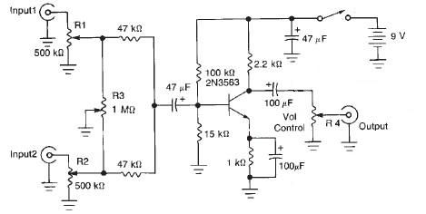
This audio mixer circuit diagram electronic project is designed using a few common electronic components. The audio mixer circuit project has two input channels. The input signal can be independently controlled using the R1 and R2 variable resistors. The...
Most of the power supply failure indicator circuits need a separate power supply for themselves. But the alarm circuit presented here needs no additional supply source. It employs an electrolytic capacitor to store adequate charge, to feed power to...
The yellow wires on the far right serve as temporary power connections, allowing battery power to enter through the contact studs located in the large holes that press against the radio's battery terminals. The cable in the lower right...
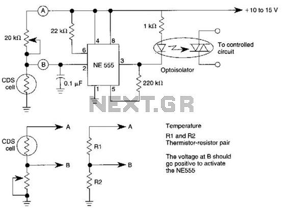
This dark-activated relay switch can be utilized to activate walkway or other outdoor lighting at dusk. By employing alternate connections to points A and B, it is capable of sensing varying levels of illumination, as well as high and...
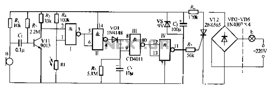
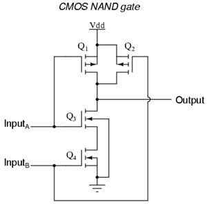
The CDI011 integrated circuit is designed for a sound and light-controlled stair delay switch circuit, which is relatively simple and effective. It utilizes a combination of NAND gates and differential input dynamics. The circuit has two input terminals; when...
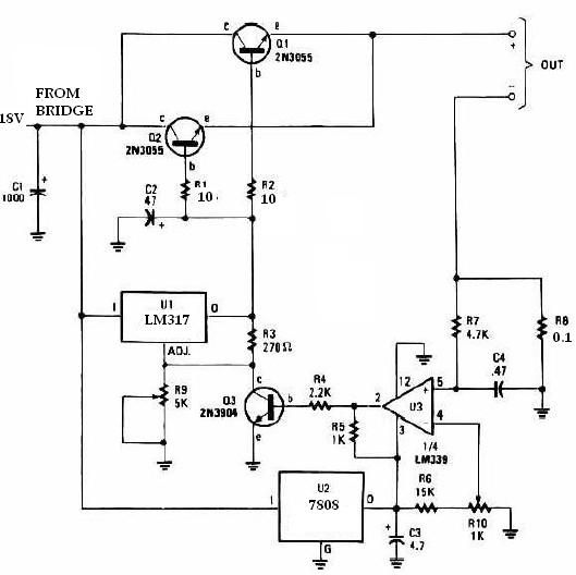
This universal battery charger utilizes the LM317 voltage regulator and features an adjustable output voltage along with a constant-current charging circuit, making it suitable for charging most NiCad batteries and various other battery types. The LM317 universal battery charger...