
2N3055 and LM723 3-30 V/2.5 A Stabilized power supply
The circuit design incorporates several critical components that contribute to its functionality and reliability. The LM723 voltage regulator serves as the heart of the power supply, providing a stable output voltage that can be finely tuned. The Darlington pair configuration, consisting of BD135 and 2N3055 transistors, allows for significant current amplification, enabling the circuit to handle higher loads while maintaining the desired output voltage range.
Resistor R5 plays a vital role in the protection mechanism of the power supply. By monitoring the current flowing through the circuit, it ensures that if the current exceeds safe limits, the circuit is automatically disabled, preventing damage to both the power supply and connected loads. This self-protective feature is crucial in maintaining the longevity and safety of the power supply in various operational conditions.
The potentiometer P1 is an essential user interface element, enabling operators to set the output voltage according to specific requirements. This adjustability makes the power supply suitable for a wide range of applications, from powering small electronic devices to testing and prototyping in more complex circuits.
The transformer selection is also a key consideration; using a transformer with the appropriate secondary voltage rating ensures that the circuit can achieve its full potential. The requirement for the rectified voltage to exceed the maximum output by 4-5 volts is necessary to account for voltage drops across the rectifying diodes and any filtering capacitors, ensuring that the output remains stable under load.
Overall, this versatile power supply circuit is an invaluable tool for electronics professionals, providing a reliable and adjustable source of power for various applications. Its thoughtful design, incorporating protection features and user-friendly adjustments, makes it a practical solution for everyday needs in electronics workshops.This is a very useful project for anyone working in electronics. It is a versatile power supply that will solve most of the supply problems arising in the everyday work of any electronics work shop. It covers a wide range of voltages being continuously variable from 30 V down to 3 V. The output current is 2. 5 A maximum, more than enough for most a pplications. The circuit is completely stabilised even at the extremes of its output range and is fully protected against short-circuits and overloading. The power supply is using a well known and quite popular VOLTAGE STABILIZER IC the LM 723. The IC can be adjusted for out put voltages that vary continuously between 2 and 37 VDC and has a current rating of 150 mA which is of course too low for any serious use.
In order to increase the current handling capacity of the circuit the output of the IC is used to drive a darlington pair formed by two power transistors the BD 135 and the 2N3055. The use of the transistors to increase the maximum current output limits the range of output voltages somewhat and this is why the circuit has been designed to operate from 3 to 30 VDC.
The resistor R5 that you see connected in series with the output of the supply is used for the protection of the circuit from overloading. If an excessively large current flows through R5, the voltage across it increases and any voltage greater than 0.
3 V across it has as a result to cut the supply off, thus effectively protecting it from overloads. This protection feature is built in the LM 723 and the voltage drop across R5 is sensed by the IC itself between pins 2 and 3. At the same time the IC is continuously comparing the output voltage to its internal reference and if the difference exceeds the designerG ‚¬ s standards it corrects it automatically.
This ensures great stability under different loads. The potentiometer P1 is used to adjust the out put voltage at the desired level. If the full range from 3 to 30 V is desired then you should use a mains transformer with a secondary winding having a rating of at least 24 V/3 A. If the maxi mum voltage output is not desired you can of course use a transformer with a lower secondary voltage output.
(However, once rectified the voltage across the capacitor C2 should exceed by 4-5 volts the maximum output expected from the circuit. 🔗 External reference
Related Circuits
This is a light dimmer circuit. It does not include any special features and is a typical TRIAC-based dimmer circuit. This circuit is designed to operate with... A TRIAC-based light dimmer circuit is a common electronic design used to control...
This circuit utilizes a 13-volt zener diode (D2) for voltage regulation. Approximately 0.7 volts are dropped across the base-emitter junction of the transistors, resulting in a higher current output of 12.3 volts. The circuit is capable of supplying loads...
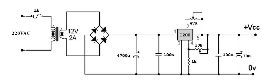
A variable power supply based on the L200 IC, where the output voltage is controlled by a 10K variable resistor. The output voltage ranges from approximately 3 to 15 volts, with a current output ranging from a minimum of...
The NE568A (NE568AD, NE568AN, SA568AD, SA568AN) is a monolithic phase-locked loop (PLL) that operates from 1Hz to frequencies exceeding 150MHz. It features an extended supply voltage range and a lower temperature coefficient of the VCO center frequency compared to...
The following circuit illustrates a Single Supply Phase Locked Loop Circuit Diagram. This circuit is based on the LM331 integrated circuit. Features include the response of... The Single Supply Phase Locked Loop (PLL) circuit utilizing the LM331 integrated circuit is...
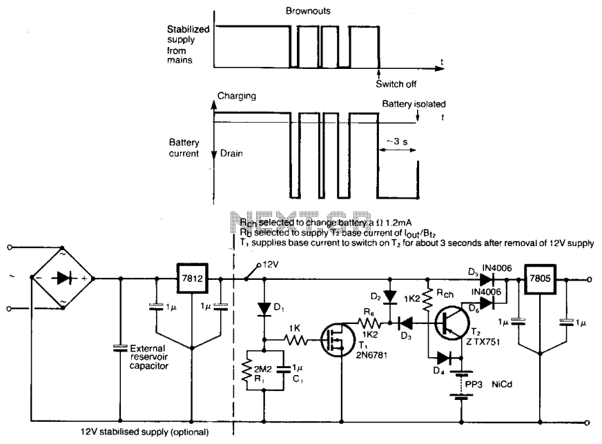
This circuit protects microprocessor systems from brownouts without the cost of an uninterruptible power supply. It is designed around a small 9-V nickel cadmium battery, which continues to provide a constant 5-V output during brownouts lasting up to a...