
12V DC Fluorescent Lamp Circuit
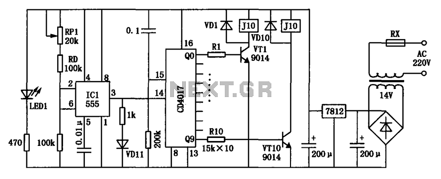
The driver circuit for a 12V, 5W fluorescent lamp is designed to efficiently convert high voltage AC power to a lower voltage suitable for the lamp operation. The use of a standard 220V to 10V step-down transformer in reverse is a practical approach, as it allows for the manipulation of voltage levels without the need for additional complex circuitry.
The circuit typically consists of the following components: a transformer, a rectifier, a filter capacitor, and a ballast resistor. The transformer is connected to the AC mains supply, and when operated in reverse, it steps down the voltage to 12V. The output from the transformer is then fed into a rectifier circuit, which converts the AC voltage to DC. A common choice for the rectifier is a bridge rectifier configuration, which ensures that the output is smooth and stable.
Following the rectifier, a filter capacitor is employed to eliminate any remaining ripple in the DC output, providing a more stable voltage for the fluorescent lamp. The value of the filter capacitor must be selected carefully to balance between size and performance, ensuring that the output voltage remains within acceptable limits for the lamp.
The ballast resistor is essential for controlling the current flowing through the fluorescent lamp, preventing it from drawing excessive current, which could lead to damage or reduced lifespan. The resistor value is determined based on the specifications of the lamp and the desired operating conditions.
This circuit design is advantageous due to its simplicity and the availability of standard components, making it accessible for various applications. Care should be taken during the implementation to ensure that all components are rated appropriately for the voltages and currents involved, as safety is paramount when working with electrical circuits.In this article I will offer driver circuit for 12 V/5Watt fluorescent lamp, this circuit used a normal 220 to 10V stepdown transformer in reverse to step 12V. 🔗 External reference
Related Circuits
Modern exhibitions utilize extensive sound, light, and electrical technologies for advertising, promotion, and propaganda. This involves various electrical diagrams and control models. Commonly used is an automatic program circuit with pre-recorded commentary, which requires synchronization of two mating times....

A passive high-pass filter has been added after the output of the operational amplifier (op-amp) to eliminate DC offset, with the op-amp powered by +12V and the negative supply at 0V. A feedback resistor (Rf) of 500K Ohms is...
All sound effects are generated internally by the HT2884 integrated circuit (IC). The device operates on a 3-volt battery but is compatible with any voltage ranging from 2.5 to 5 volts. Switch S1 functions as the on/off switch. The...
This circuit converts 12V DC into 220V AC. It utilizes a 4047 integrated circuit to generate a 50Hz square wave, which is then used to amplify the current and subsequently increase the voltage using a step-up transformer. The circuit...
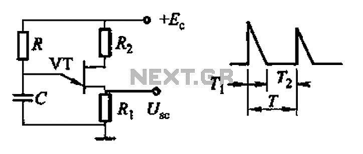
Common non-sinusoidal oscillator circuit, waveform and frequency formula - pulse wave oscillator - blocking oscillator transformer The common non-sinusoidal oscillator circuit is designed to generate pulse waveforms, which are characterized by their square or rectangular shape. These oscillators are...
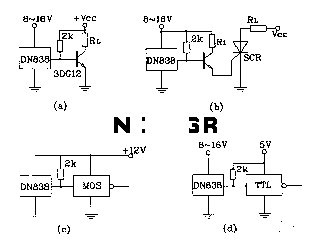
Figures (A), (B), (C), and (D) illustrate outputs that can directly drive transistors, thyristors, relays, CMOS circuits, and TTL circuits. The described figures depict various output configurations capable of interfacing with different electronic components. Each output is designed to provide...
Warning: include(partials/cookie-banner.php): Failed to open stream: Permission denied in /var/www/html/nextgr/view-circuit.php on line 713
Warning: include(): Failed opening 'partials/cookie-banner.php' for inclusion (include_path='.:/usr/share/php') in /var/www/html/nextgr/view-circuit.php on line 713