
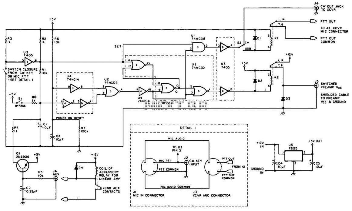
Synchronous controller circuit diagram of a recording transcript

The described system integrates multiple technologies to enhance the effectiveness of modern exhibitions. The automatic program circuit is designed to play pre-recorded audio commentary in conjunction with visual displays, creating an immersive experience for the audience. This circuit typically involves a microcontroller or programmable logic device (PLD) that manages the playback of audio files stored in a digital format.
The synchronization of two mating times is critical for ensuring that the audio commentary aligns perfectly with the visual elements of the exhibition. This can be achieved through a synchronous controller circuit, which may utilize a combination of timers, counters, and control logic to coordinate the timing of audio playback with other events in the exhibition.
The electrical diagrams for this system would include representations of the power supply, signal flow, and control logic. Key components may include audio amplifiers, speakers, and light control circuits, which are all integrated to work in unison. The use of light and sound in a synchronized manner not only captures attention but also reinforces the message being conveyed through the exhibition.
In summary, the modern exhibition circuit design incorporates advanced technologies and precise timing mechanisms to deliver a cohesive and engaging experience, making use of both electrical engineering principles and creative design to achieve its objectives.Activities Modern exhibition, advertising, promotion and propaganda extensive use of sound, light, electricity technology, a number of electrical diagrams, control model, commo nly used automatic program circuit with pre-recorded commentary, then asked the two mating time required to achieve synchronization. Shown for the recording transcript synchronous controller circuit.
Related Circuits
This circuit is beneficial for amateur radio operations in VHF and UHF frequencies, where a mast-mounted antenna preamplifier is employed for reception. The kit manages the transmit-receive (T-R) switching and relay sequencing to prevent high RF levels from being...
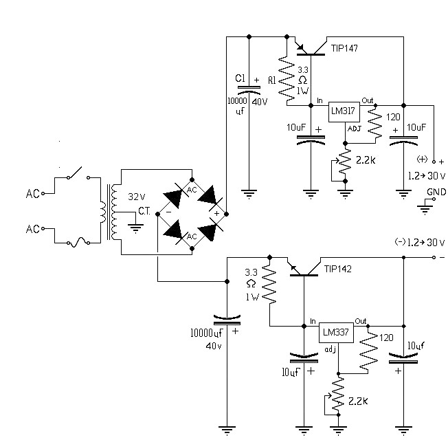
The 10A variable power supply circuit is symmetrical and can provide a symmetrical output voltage ranging from ±1.2 volts to ±30 volts DC, with a maximum current of 10A. This circuit utilizes symmetrical variable voltage regulators LM317 and LM337,...

The LED running light project can be easily implemented using microcontrollers, particularly the Microchip PIC microcontroller. This project utilizes the PIC16F877A microcontroller, which features a 40-pin IC configuration, with LEDs connected to port B. The LEDs twinkle in accordance...
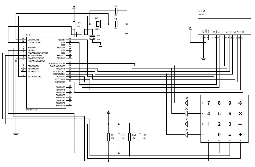
A beginner or hobbyist is seeking to learn more about microcontrollers. The objective is to display an output on an LCD when a button on the keypad is pressed. To achieve the desired functionality of displaying output on an LCD...
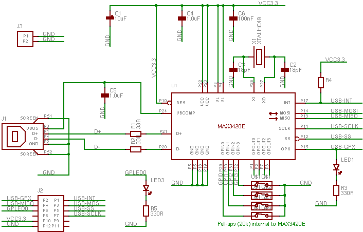
The MAX3420 is a USB peripheral controller chip featuring an SPI bus. This document aims to provide sufficient information for effective utilization of the device in various projects. The MAX3420 simplifies the integration of a USB interface into a...
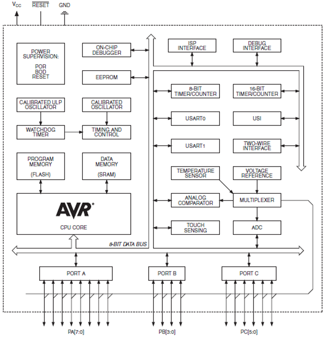
The ATtiny1634 8-Bit AVR Microcontroller from Atmel is based on the enhanced RISC architecture of AVR. It can execute powerful instructions in a single clock cycle, achieving throughputs close to 1 MIPS per MHz. This allows system designers to...