
12V Flourescent Lamp Inverter
The circuit design for operating fluorescent tubes from a battery source involves a sophisticated inverter system to ensure efficient power conversion and optimal light output. The DC-DC inverter, consisting of integrated circuits (ICs) and transistors, is responsible for stepping up the input voltage from the battery to a level suitable for energizing the fluorescent tubes.
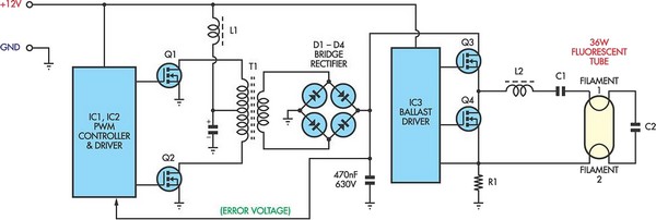
The first stage of the inverter employs a pulse-width modulation (PWM) technique to control the switching of transistors Q1 and Q2, which alternately connect the battery voltage to the transformer. This transformer steps up the voltage to the necessary high-voltage AC required by the fluorescent tubes. The secondary side of the transformer feeds into the fluorescent tube driver circuit, which utilizes IC3 along with transistors Q3 and Q4 in a totem-pole configuration to generate the alternating current (AC) required for the tubes to operate efficiently.
It is essential to note that the inverter's efficiency plays a critical role in the overall performance of the fluorescent lighting system. Losses in the inverter can lead to insufficient power being delivered to the tubes, resulting in diminished light output. The design should consider the thermal management of the components, as excessive heat can further degrade performance and reliability.
Safety precautions are paramount when constructing this circuit, given the high-voltage output exceeding 300V DC. Proper insulation, protective enclosures, and adherence to electrical safety standards are crucial to prevent electrical shock hazards. Only qualified personnel with experience in handling high-voltage circuits should attempt to assemble or modify this system.
In summary, while fluorescent lighting offers numerous advantages in terms of efficiency and longevity, careful consideration must be given to the design and implementation of the inverter circuit to ensure optimal performance and safety.Fluorescent tubes use far less energy than incandescent lamps and fluorescent tubes last a great deal longer as well. Other advantages are diffuse, glare-free lighting and low heat output. For these reasons, fluorescent lighting is the natural choice in commercial and retail buildings, workshops and factories.
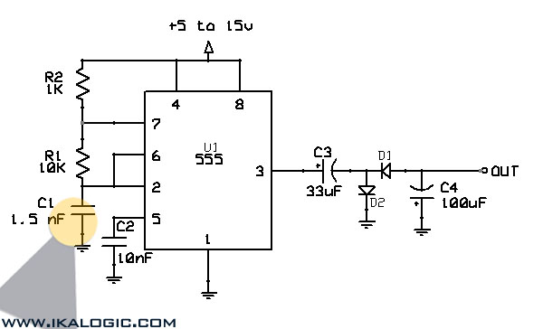
For battery-powered lighting, fluores cent lights are also the first choice because of their high efficiency. The main drawback with running fluorescent lights from battery power is that an inverter is required to drive the tubes. Fig. 1: two switch-mode circuits are involved here: the DC-DC inverter involving IC1, Q1 & Q2 and the fluoro tube driver which converts high voltage DC to AC via IC3 and Q3 & Q4 in a totem-pole circuit.
Inverter efficiency then becomes the major issue. There are many commercial 12V-operated fluorescent lamps available which use 15W and 20W tubes. However, it is rare to see one which drives them to full brilliance. For example, a typical commercial dual 20W fluorescent lamp operating from 12V draws 980mA or 11. 8W. Ignoring losses in the fluorescent tube driver itself, it means that each tube is only supplied with 5. 9W of power which is considerably less than their 20W rating. So while the lamps do use 20W tubes, the light output is well below par. This circuit generates in excess of 300V DC which could be lethal. Construction should only be attempted by those experimenced with mains-level voltages and safety procedures
🔗 External reference
Related Circuits
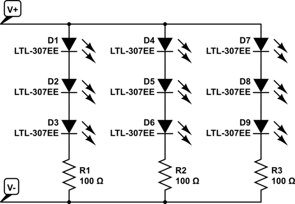
The project involves installing LED strips in a car's tail lamps to replace conventional bulbs. The required lengths for the LED strips are 16 inches, 15 inches, and 14 inches to fit properly within the housings. The selected LED...
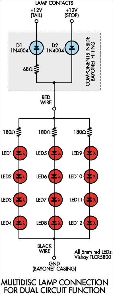
Before proceeding with the implementation, it is important to ensure that the output brightness is adequate for a stop and tail-light application. The light output may vary based on the tail-light lens and reflector assembly, so caution should be...
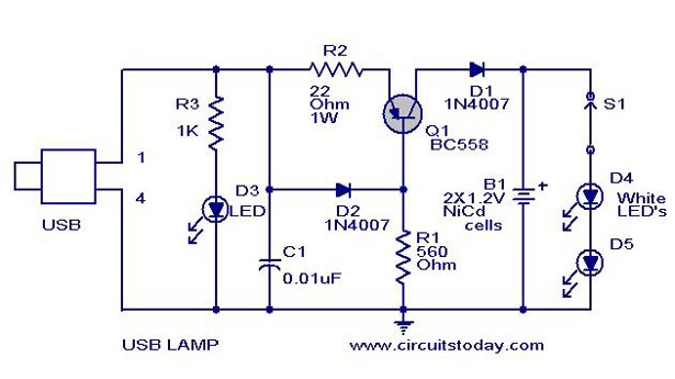
A simple USB LED lamp circuit utilizing a 5-volt power supply sourced from a USB port, designed to illuminate a desktop or laptop computer during power outages. The USB LED lamp circuit operates by converting the 5-volt DC power provided...
This circuit converts a positive voltage to a negative voltage, resulting in a loss of approximately 1.5 V. For instance, supplying 9 V to the circuit yields an output of -7.5 V. Additionally, this circuit can function as a...
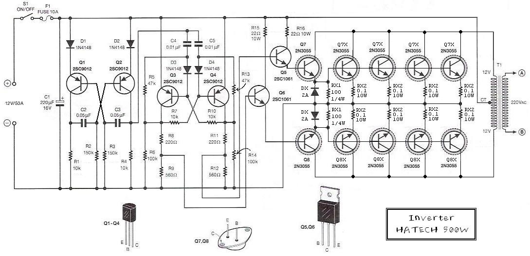
This is the schematic diagram of a 500W power inverter circuit built using 10 pieces of well-known NPN power transistors, 2N3055, to amplify the AC signal produced by a multivibrator. The frequency generator/multivibrator is also constructed using transistors. All...

The following circuit illustrates an Elektroblock circuit diagram utilizing a 12V power supply. Features include various control and monitoring functions, with the specification of an 18 A LAS 1218 component. The Elektroblock circuit is designed to operate with a 12V...