
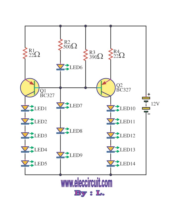
12V Light Dimmer Circuit
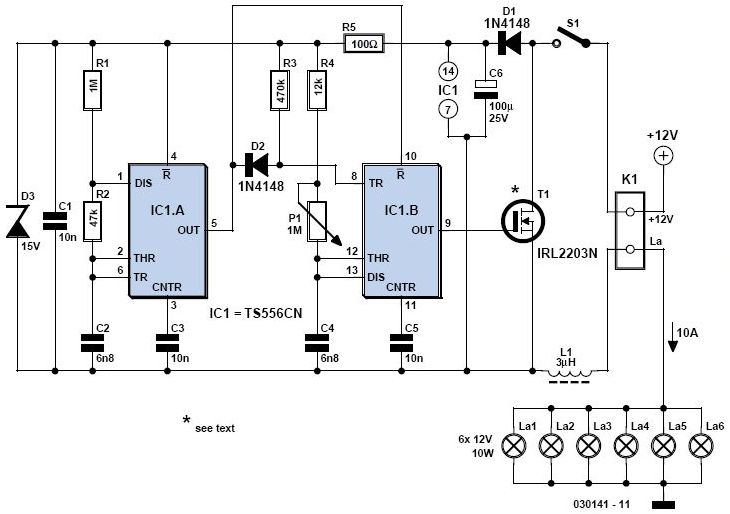
A light dimmer circuit is an essential component for enhancing the ambiance in confined spaces such as caravans and boats. This circuit allows users to adjust the brightness of lighting fixtures, contributing to a more comfortable and personalized environment. The design of a light dimmer typically involves the use of a variable resistor or a solid-state device, such as a triac, which regulates the power delivered to the light source.
In a basic dimmer circuit, the primary components include a triac, an optoisolator, a variable resistor (potentiometer), and a few passive components like resistors and capacitors. The triac serves as a switch that can control the AC voltage supplied to the light bulb. By adjusting the variable resistor, the phase angle of the AC signal can be altered, effectively reducing the voltage and current flowing to the light fixture, which dims the light output.
The optoisolator is used to provide electrical isolation between the control circuit and the high-voltage AC circuit, enhancing safety. It allows a low-voltage control signal to trigger the triac without direct electrical connection, minimizing the risk of electric shock.
In terms of implementation, the circuit can be connected in series with the light load. When the potentiometer is adjusted, it changes the trigger point of the triac, thus controlling when the triac turns on during each AC cycle. This method is efficient and allows for smooth dimming without flickering.
Overall, the integration of a light dimmer in a caravan or boat not only increases the versatility of lighting options but also contributes to energy savings and extended lifespan of lighting elements.A light dimmer is quite unusual in a caravan or on a boat. Here we describe how you can make one. So if you would like to be able to adjust the mood when y.. 🔗 External reference
Related Circuits
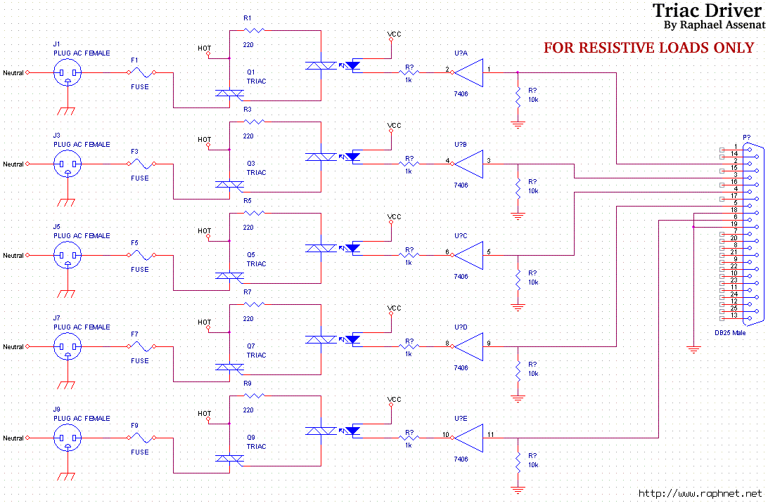
Controlling room lighting using a computer. Triacs and opto-couplers have been purchased for this purpose. A schematic was drawn and a prototype was built, which functioned correctly. Although not visible in the pictures, there is a cable extending from...
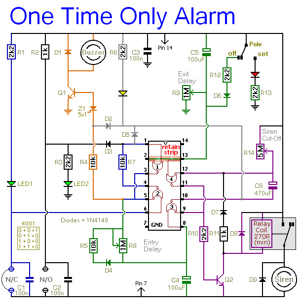
This alarm is designed to activate its siren only once. When the alarm is triggered, the siren will sound for a predetermined duration before automatically turning off and remaining inactive. The alarm system features a single zone with independently...
The circuit is designed to be powered directly by a power supply, which is why it does not include a transformer, rectifier, or filter capacitors in the schematic. However, these components can be added if desired. To operate the...
The PLL synthesizer oscillator circuit is a feedback loop consisting of a reference oscillator, phase comparator, loop filter, voltage-controlled oscillator, programmable frequency divider, and various other components. In this circuit, the reference oscillator employs a crystal oscillator (OSC) to...
Electric single-girder cranes, also known as electric hoists, are commonly utilized in small factories for lifting and handling equipment. Typically, they are used in conjunction with drag line switching operation, which may not be very convenient. The circuit includes...
This circuit enables the brake light to flash. The default behavior occurs when power is supplied to the circuit or when the brake is engaged. The timer IC (IC2) drives current to the transistor (Q2), producing an oscillating output...
Warning: include(partials/cookie-banner.php): Failed to open stream: Permission denied in /var/www/html/nextgr/view-circuit.php on line 713
Warning: include(): Failed opening 'partials/cookie-banner.php' for inclusion (include_path='.:/usr/share/php') in /var/www/html/nextgr/view-circuit.php on line 713