
OP113 wide range of precision temperature measurement circuit

The described circuit employs a K-type thermocouple, which is widely used for temperature measurement due to its broad temperature range and good accuracy. The cold junction compensation is essential for ensuring accurate readings, as it accounts for the temperature at the junction where the thermocouple connects to the measurement system. The reference voltage source provides a stable voltage that is critical for the proper functioning of the operational amplifier, ensuring that the output remains linear and precise across the temperature range.
The OP113 operational amplifier is selected for its low drift characteristics, which minimize errors in the output signal due to temperature variations and component aging. This is particularly important in precision applications where even minor drift can lead to significant measurement inaccuracies. The low noise specification of the OP113 allows for clearer signal amplification, which is vital when dealing with the small voltage outputs typical of thermocouples.
The configuration of the circuit allows for high-gain amplification of the thermocouple signal, translating small changes in temperature into a measurable voltage output. The output voltage range of 0V to 10.000V corresponds to the temperature range of 0°C to 100°C, making it suitable for various applications in industrial and laboratory settings. The bandwidth of 3.4MHz ensures that the circuit can respond quickly to changes in temperature, making it effective for dynamic temperature monitoring.
Overall, this circuit design effectively combines the K-type thermocouple with a precision reference voltage and a high-performance operational amplifier to achieve accurate and reliable temperature measurements.The circuit consists of K-type thermocouple cold junction compensation circuit, precision 5. OOOV reference voltage source and OP113 composition, can o-lOooqc to measure the temperature, the temperature resolution of 0.02cC. OP113 wide range of precision temperature measurement circuit in Figure 1-18 below. K thermocouple temperature detection object to be measured, VD, and the like cold junction compensation, IC1 provides 5.OOV reference power. OP113 low drift (maximum voltage drift lOOmV, maximum drift 0.2mV / ), low noise, wide (3. 4MHz) operational amplifier, here for high-gain amplifier, when the temperature changes within a 0 lOooqC, output voltage O ~ 10.
OOV.
Related Circuits
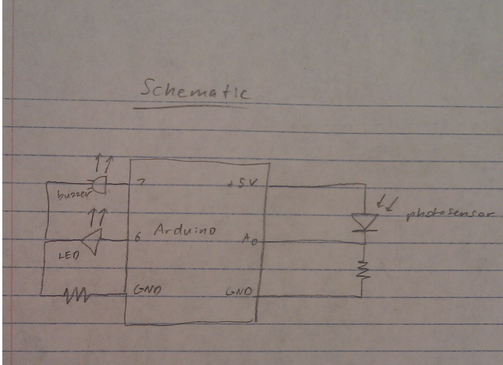
A nightlight combined with a wake-up alarm has been developed. This nightlight incorporates six LEDs that activate when a photosensor detects low ambient light levels. Additionally, a buzzer plays a cheerful tune when ambient light levels increase again. The...
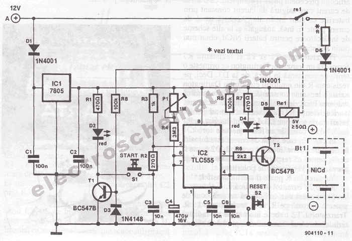
The portable battery charger has been designed to enable the charging of NiCd batteries outdoors using a 12 V vehicle battery. The portable battery charger is engineered to facilitate the charging of Nickel-Cadmium (NiCd) batteries in outdoor environments, leveraging the...
Today, it is no longer necessary to use discrete components for constructing oscillators. Many manufacturers now offer ready-made voltage-controlled oscillator (VCO) integrated circuits (ICs) that require only a few external components to determine the frequency. An example of such...
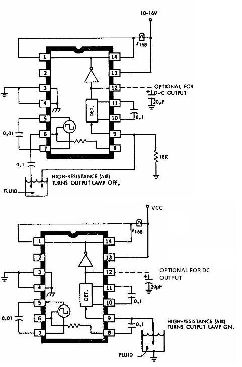
This electronic liquid detector circuit diagram is based on the ULN2429 monolithic bipolar integrated circuit designed for detecting the absence or presence of many different types of liquids. The ULN2429 electronic liquid detector circuit can be used in automotive,...
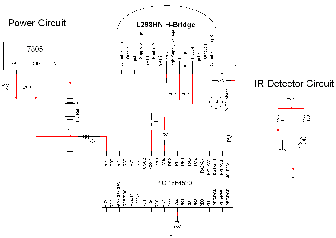
The simple motor optical encoder circuit is not particularly difficult; however, it requires careful verification to ensure all connections are correct before initial operation. The primary components utilized in the circuit include the 7805 voltage regulator, the PIC18F4520 microcontroller,...
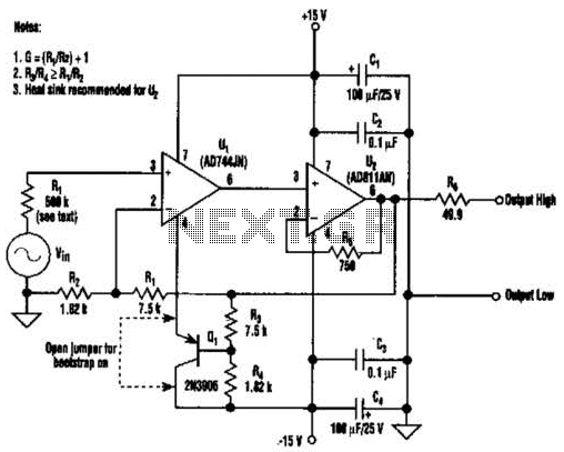
Bootstrapping the substrate of a JFET amplifier minimizes distortion resulting from the non-linearity of the JFET input capacitance. In the accompanying figure, a secondary feedback divider is used to bootstrap the substrate of U1, with R1 set to 500...