
LEDs or lamps sequencer circuit
The described circuit operates within a specified voltage range, allowing for flexibility in the number of LEDs or bulbs utilized. The series connection of LEDs is a common practice in LED applications, ensuring that the voltage across each LED remains within its rated limits. Careful selection of the power supply voltage is essential to prevent exceeding the maximum ratings of the LEDs, which can lead to failure or reduced lifespan.
In instances where incandescent bulbs are used, the circuit design must account for the higher current draw, particularly when multiple bulbs are connected in series. The use of Darlington transistors is advantageous in high-current applications due to their ability to amplify current, thereby allowing for the control of larger loads without excessive heat generation in the driving transistor. The omission of R1 when using Darlington transistors simplifies the design and reduces component count, which can lead to a more compact and efficient circuit.
The sequencer circuit's functionality is enhanced through the adjustment of capacitor C1, which influences the timing and speed of the LED sequence. This feature is particularly useful in applications requiring dynamic visual effects, such as advertising displays or interactive game interfaces. By integrating this circuit into toys, manufacturers can create engaging experiences for children, combining visual stimulation with interactive play.
Overall, the design considerations for this circuit encompass not only the electrical parameters but also the intended application, ensuring that the final product meets both performance and user engagement requirements.A voltage ranging from 6 V to 15 V is supplied if only one LED per module is used. The increase in the number of LEDs also corresponds to the increase of voltage supply and the connection of additional LEDs should be in series. The maximum allowed voltage is 24 V which could cater approximately 10 LEDs in series connection. A 15 V supply can handle around 7 LEDs while a 12 V supply can handle no more than 5 LEDs. The color and brightness are the factors which the right number of LEDs depend on. In using a bulb or incandescent lamp, the supply of voltage can range from 9 V to 24 V. For 24 V supply, four 6 V bulbs can be connected in series. The use of bulbs with more than 400 mA of current consumption would cause the transistor BC337 to be changed with Darlington types like 2N6037 to 2N6039, BD677, BD679, BD681, and other similar types. The number of parts will be reduced if Darlington transistors were used since R1 can be omitted because of the built-in base-emitter resistor.
The speed or frequency of the sequencer may be varied with the changing of the value of C1. The LED or lamp sequencer circuit can provide more attraction in advertising as it provides more animation. It was also used in interactive games from an old TV program where you have to press a letter and the sequence of LEDs follow a path up to the main screen which will tell if you pressed the right or wrong letter.
It can also be used to provide entertainment for children by placing the circuit in toys such as robots and toy guns. 🔗 External reference
Related Circuits

This design circuit is for audio graphic equalizers, which are commonly found in commercial products, yet circuits for them are rarely published. The circuit features a simple design that requires an operational amplifier (op-amp) to amplify the input signal....
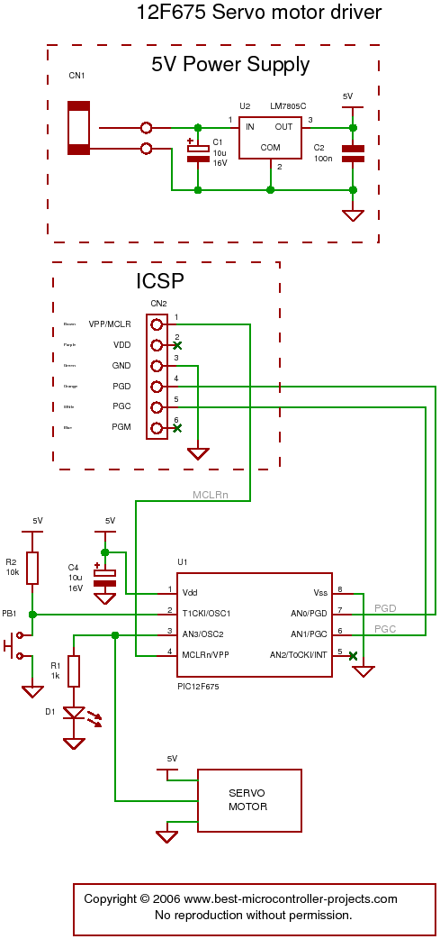
The following circuit illustrates a servo motor driver. This circuit is based on the 12F675 IC. Features include Timer 0 timing and a single control line. The servo motor driver circuit utilizing the 12F675 integrated circuit (IC) is designed to...

This is a simple yet effective charger for lead-acid batteries. It utilizes a 12-volt car bulb as both a current regulator and a charge status indicator. The described circuit is an innovative approach to charging lead-acid batteries. It employs...
This oscillator is a variation of the oscillator presented by Ulrich L. Rohde, DJ2LR, in his article "Evaluating Noise Sideband Performance in Oscillators," published in Ham Radio, October 1978, Page 51. The original circuit can be found at the...
You may be familiar with this effect. You switch audio equipment such as an amplifier to a different input and there is a loud click or "thump" in the speaker system. Not all equipment is affected. Some high-end audio...
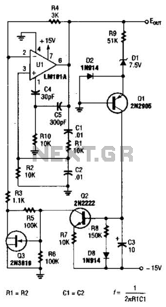
For variable-frequency operation, Rl and R2 can be replaced by a dual potentiometer. In electronic circuits that require variable-frequency operation, the use of a dual potentiometer as a replacement for resistors Rl and R2 can provide enhanced functionality and flexibility....