
12v to 120v voltage inverter circuit
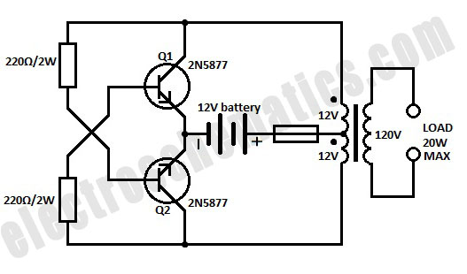
The 12V inverter circuit operates by leveraging a push-pull configuration facilitated by the two transistors, Q1 and Q2. The center-tapped transformer plays a crucial role in this setup, allowing for efficient conversion of the DC input voltage into an AC output. The initial activation of Q1 establishes a magnetic field in the transformer, which then induces a voltage in the secondary winding. The output waveform is a square wave, characterized by its rapid transitions between high and low states, making it suitable for applications that do not require a pure sine wave.
The self-oscillating nature of the circuit ensures that once initiated, it continues to operate without external triggering. The design incorporates feedback through the transformer, which stabilizes the oscillation frequency. The frequency stability is particularly important in applications where timing is critical.
The output power capability of up to 20W indicates that this inverter is designed for low-power applications. The choice of components, particularly the transistors, should consider their current and voltage ratings to ensure reliable operation. The inverter's limitation regarding reactive loads is a significant consideration for users, as inductive loads can result in high inrush currents that exceed the circuit's capacity, potentially damaging the transistors or leading to circuit failure.
For applications requiring higher power output, the circuit can be scaled by using transformers with higher power ratings and transistors capable of handling greater current loads. Additionally, careful attention must be paid to heat dissipation, as increased power can lead to thermal issues if not managed properly.
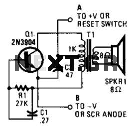
In summary, this 12V inverter circuit provides a straightforward solution for generating low-voltage AC power from a DC source, suitable for various portable electronic devices while maintaining simplicity and efficiency in its design.A simple 12 volt inverter circuit. This 120V AC power source is built with a simple 120V:24V center-tapped control transformer and four additional component. This circuit outputs a clean 200-V pk-pk square wave at 60 Hz and can supply up to 20W. The circuit is self-starting and free-running. If Q1 is faster and has a higher gain than Q2 is will turn on first when you apply the input power and will hold Q2 off. Load current and transformer magnetizing current then flows in the upper half of the primary winding, and auto transformer action supplies the base drive until the transformer saturates. When that action occuts, Q1 loses its base drive. As it turns off, the transformer voltage reverse, turning Q2 on and repeating the cycle. The output frequency depends on the transformer iron and input voltage but not on the load. The frequency range between 50 to 60 Hz with a 60-Hz transformer and car battery or equivalent source.
The output voltage depends on turns ratio and the difference between input voltage and transistor saturation voltage. For higher power, use larger transformers and transistors. This type of 12V inverter normally is used in radios, phonographs, hand tools, shavers and small fluorescent lamps.
It will not work with reactive loads (motors) or loads with inrush currents, such as coffee pots, frying pans and heaters. 🔗 External reference
Related Circuits
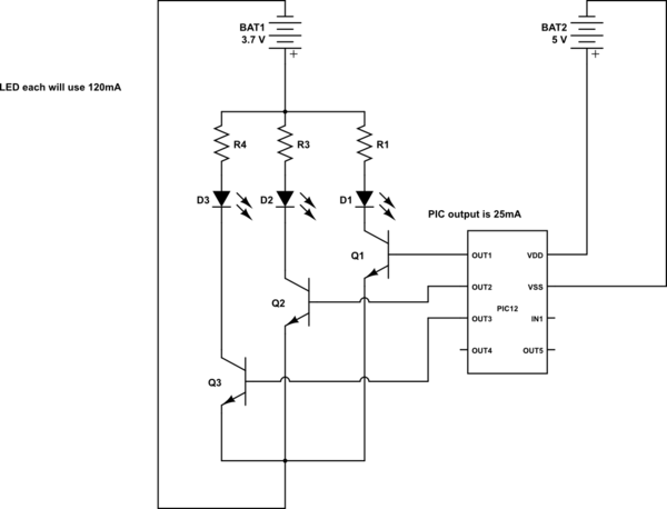
This is a conceptual schema utilizing a PIC12 microcontroller to control the blinking of three LEDs, each exhibiting different blinking patterns. There are several questions that need to be addressed. The circuit design involves a PIC12 microcontroller, which is a...
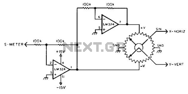
To display polar quantities, which include both the magnitude and direction of a received radio signal, a sine and cosine voltage proportional to an angle corresponding to the antenna direction is required. This setup utilizes a sine-cosine potentiometer connected...
Creating circuit boards can be a challenging task. It requires designing a schematic, testing it on a breadboard, laying out the board, and finally printing and etching the board. Fortunately, Fritzing offers a solution. Fritzing is a free, open-source...
This is a simple low-level noise maker that is ideally suited for certain alarm applications. When the sounder is located in another part of the building, the sound level is loud enough to be heard but is not loud...
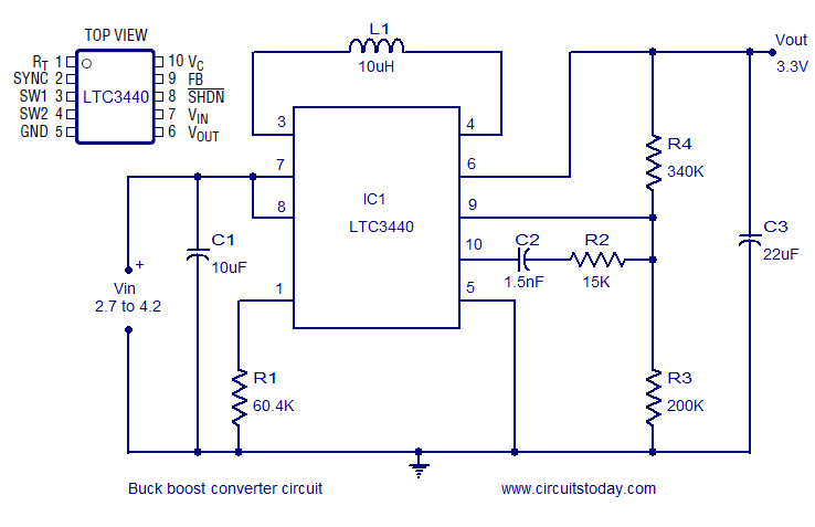
A simple and highly efficient buck-boost converter is implemented using the LTC3440 integrated circuit. The output voltage is set at 3.3V, while the input voltage range can vary from 2.7V to 4.2V. The LTC3440 is a synchronous buck-boost converter designed...
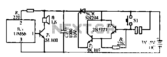
A few custom integrated circuits began to play music. When the song ends, no electricity flows through the thyristor, which then cuts off the light, causing the phototransistor to activate. The system is designed with a touchpad; each touch...