
Low Level Sounder Circuit

The described circuit utilizes a 2N3904 NPN transistor as the active component in a Hartley oscillator configuration, which is known for its simplicity and effectiveness in generating audio frequencies. The Hartley oscillator consists of an inductor and a capacitor that form the resonant tank circuit, enabling the generation of oscillations. In this case, the oscillator is configured to produce a tone suitable for alarm purposes.
The output from the transistor is fed into a transformer, which serves to match the output impedance to the load and can also amplify the signal. The transformer has a primary winding connected to the collector of the transistor and a secondary winding that drives the sounder. The choice of a 1 kΩ to 8Ω transformer indicates that the circuit is designed to work with low-impedance sounders, ensuring effective sound production.
The frequency of the generated tone is determined by the values of R1 (the resistor) and C1 (the capacitor). By altering the resistance or capacitance, the oscillation frequency can be adjusted. Specifically, increasing the resistance or capacitance will lower the frequency, while decreasing either will raise the frequency. This tunability allows for the customization of the sound produced, enabling it to be tailored for specific alarm applications.
It is critical to observe the recommendation regarding the minimum value for R1. A resistance value lower than 4.7 kΩ could lead to excessive current through the transistor, potentially resulting in thermal overload and damage to the device. Therefore, careful selection of R1 and C1 is essential for both functionality and reliability of the circuit.
In summary, this low-level noise maker circuit is a practical solution for alarm systems, providing an adjustable tone output while maintaining a safe operational range for the components involved. The design's simplicity and effectiveness make it suitable for various applications within alarm systems, particularly in scenarios where a low-level alert is desired. This is a simple low-level noise maker that`s ideally suited to certain alarm applications. When the sounder is located in another part of the building, the sound level is loud enough to be heard, but is not loud enough to warn off an intruder. A single 2N3904 npn transistor is connected in a Hartley audio oscillator, with a 1 kO to 8- transistor-output transformer doing double duty.
The circuit produces a single- frequency tone that can be varied in frequency by changing the value of either or both Ri and C1. Increasing the value of either component will lower the output frequency and decreasing their values will raise the frequency. Don`t go below 4.7 kQ for Rl because you could easily destroy Ql.
Related Circuits

Small additional circuitry during standby can significantly enhance efficiency. In a modern vehicle, multiple microcontrollers are required to support safety, navigation, entertainment, and comfort electronics. The integration of additional circuitry during standby mode in automotive applications is crucial for optimizing...
The power requirements for driving light aircraft flight simulator transducers are relatively low, approximately 20W (real Watts, RMS power). It is essential to ensure that the amplifier circuit has adequate low-frequency bandwidth. Single-ended amplifiers with capacitive coupling between the...
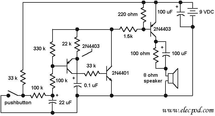
The core component of the circuit is a dual transistor flasher with frequency modulation applied to the base of the first transistor. When the pushbutton is pressed, the oscillation frequency increases to a peak, and when the button is...
The output level was set to 3.8V peak to peak. The initial objective was to compare several different operational amplifiers (op-amps) before further optimizing the circuit. The op-amps evaluated were the TL072, LM4562, and OPA2134. The distortion spectra are...
Using only a single transistor and a few passive components, a fairly sensitive peak detector circuit can be built. This peak detector circuit is suitable for various applications. The peak detector circuit utilizes a single transistor, typically configured in a...
The total electric current drawn by the circuit should be measured by connecting the probes of a multimeter across the positive output of the power supply and the positive rail input of the amplifier. The expected current value is...