
Pattern Generator For Radio Direction Finding Circuit
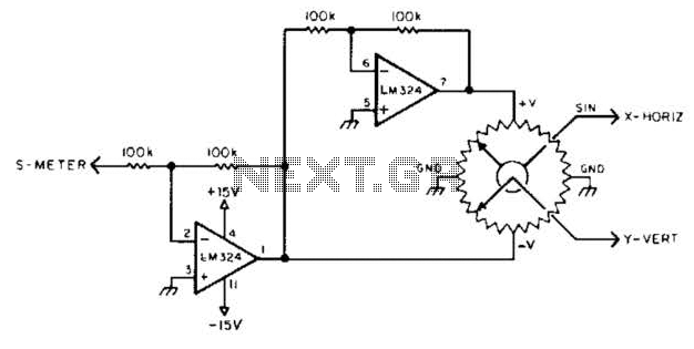
In this system, the sine-cosine potentiometer serves as a critical component that translates the angular position of the antenna into corresponding sine and cosine voltages. As the antenna is rotated to various positions, the potentiometer outputs vary, producing two voltage signals: one representing the sine of the angle and the other representing the cosine of the angle. These voltages are essential for determining the phase and amplitude of the incoming radio signal.
The directional antenna captures the radio waves, and the voltage sample derived from the received signal is processed to determine its magnitude. This voltage is usually scaled to ensure that it can be accurately compared with the outputs from the sine-cosine potentiometer. The combined information from the potentiometer and the received signal allows for a comprehensive representation of the signal's characteristics.
The display mechanism, which could be an analog or digital interface, presents the polar quantities visually, enabling users to assess both the strength and direction of the signal easily. This setup is particularly useful in applications such as radio direction finding, where understanding the orientation and intensity of signals is crucial for effective navigation and communication. In order to display polar quantities (magnitude and direction of a received radio signal), a sine and cosine voltage proportional to an angle (antenna direction) is needed. In this case, a sine-cosine potentiometer coupled to a directional antenna and a sample of a voltage proportional to received signal is used to display
relative magnitude and direction of a received signal. 🔗 External reference
Related Circuits
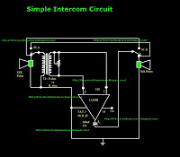
This is a simple intercom circuit utilizing the common IC LM380. In this configuration, the switch is set to the talk position for the speaker on the left, while the other participant is in the listening position. If the...
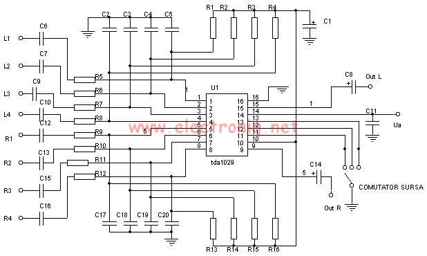
The TDA1029 is a dual operational amplifier configured as an impedance converter. Each amplifier features four mutually switchable inputs that are safeguarded by clamping diodes. Signal sources can be switched in various modes. The electronic components required for this...
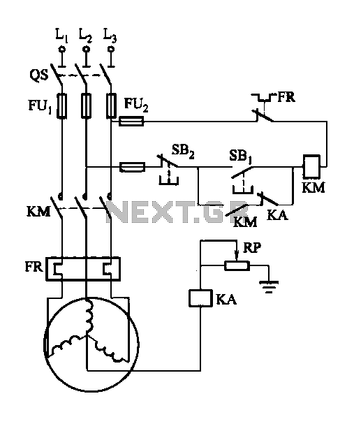
A potentiometer (RP) is utilized for adjusting the operating voltage of the relay (KA) to ensure that the motor operates normally, especially when the relay (KA) does not function reliably during the action phase. The circuit involves a potentiometer...
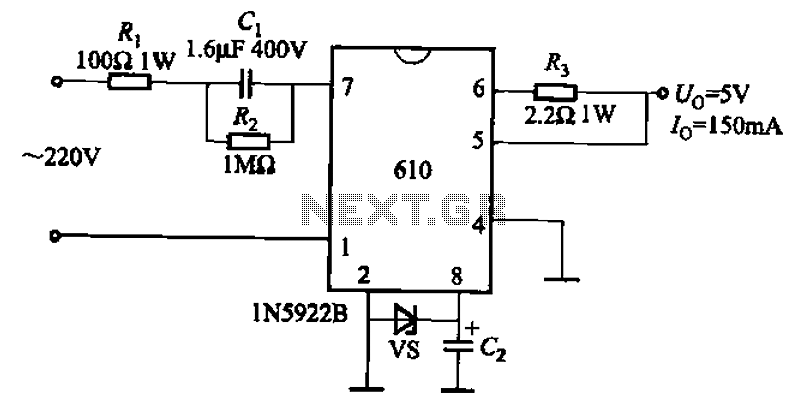
The AX610 Series has a maximum output current of 100 mA and features a scalable output current with an access regulator. The configuration includes two reverse polarity series regulators (2CW106, U: approximately 8.2V) as depicted in Figure (a). Figure...
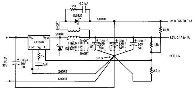
Input voltages can range from 8 V to 30 V. The load range for the 5 V output is from 0.05 A to 5 A, while the load range for the 3.3 V output is from 0.1 A to...
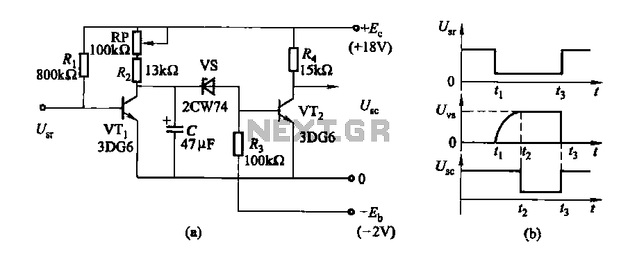
The delay time ranges from 0.5 to 3.5 seconds, which can be adjusted using the potentiometer RP to modify the delay duration. The circuit utilizes a timing mechanism that allows for the adjustment of delay intervals between 0.5 seconds and...
Warning: include(partials/cookie-banner.php): Failed to open stream: Permission denied in /var/www/html/nextgr/view-circuit.php on line 713
Warning: include(): Failed opening 'partials/cookie-banner.php' for inclusion (include_path='.:/usr/share/php') in /var/www/html/nextgr/view-circuit.php on line 713