
12v To 220v Inverter 180w By 2n3055
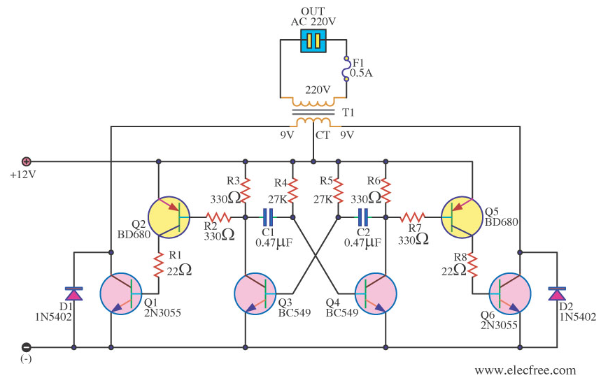
This circuit functions as a DC to AC inverter, specifically targeting applications where portable power is required. The design leverages a multivibrator configuration using transistors to create a square wave signal, which is then transformed to a higher voltage using a transformer. The choice of transistors is crucial for efficient operation; the BC549 transistors serve as the switching elements in the multivibrator, allowing for the generation of the necessary pulse signals that drive the transformer.
The transformer plays a pivotal role in stepping up the voltage from 12V to 250V AC. The configuration of the primary and secondary windings is designed to handle the power levels specified, ensuring that the circuit can deliver the required output without excessive losses. The output power ratings of 180 watts for RCA 40411 transistors and 90 watts for 2N3055 transistors highlight the importance of selecting the appropriate components based on the intended application.
Thermal management is a critical consideration in this circuit design. The use of heat sinks is essential to dissipate the heat generated by the transistors during operation, particularly when they are driven into saturation. The specified dimensions for the heat sinks ensure that the transistors remain within safe operating temperatures, thereby enhancing reliability and longevity.
The square wave output, while sufficient for basic applications, may not be compatible with all devices. Many electronic appliances, particularly those that rely on a sine wave input, may experience performance issues or may not operate at all. This limitation should be taken into account when designing systems that will utilize this inverter circuit, particularly for sensitive electronics such as audio equipment or color televisions.This circuit is converter to use to charge DC12V from the lead-acid batteries to AC 250V for use in a car, Boats or mobile homes. There are the output power There are the sufficient power to the small electronics such as a lamp or electrical soldering iron.
In circuit use only six transistors, transformer and a few electronic parts. So it is easy to build and cheap, too. The Q3(BC549) and Q4(BC549) both are the a stable multivibrator (AMV) has output is pulse square wave from about 50 Hz. They will alternately inductor current. When Q3 induct current will have the current flows through Q2, making Q1 connects the half coil circuit of the primary transformer with the 12V drop across voltage from battery.
If you use the transistor in the output section to be number: RCA 40411 will be has the current flows through the primary coil in each time is 10 amperes. To power output (Way secondary coil) is 180 watt. However, if the number 2N3055 power output will be have a 90 watt. Because transistors being used in saturation. Therefore, it must be held on a large heat sink. there is the cooling fins that size over than 100mm up and also multiple fins. And If using transformer is triodes core, it makes a smaller size. The circuit is small, because have a little device makes do no adjust to a sine wave. Thus the wave output will be a square. Which may be a result of some electrical appliances, such as, dimmer lights and electric motors, may be will not work.
Because it is designed to be used with a sine wave power, and is not recommended for use with color TV and video or audio tape. 🔗 External reference
Related Circuits

The circuit on the right uses three bipolar transistors to accomplish the same result with the touch contact referenced to the negative or ground end of the supply. Since the base of a bipolar transistor draws current and the...
This is a 220V LED flasher circuit designed as a reliable alternative to thermally activated switches used for flashing Christmas tree lamps. It is a cost-effective and easy-to-assemble circuit. The components include R1 (100K), R2 (1K), R5 (1K), R3...
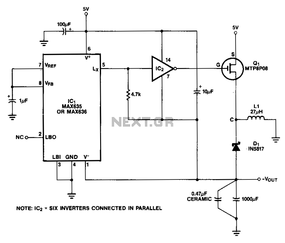
In this circuit, a CMOS inverter, such as the CD4069, is utilized to convert the open-drain Lx output into a signal that is appropriate for driving the gate of an external P-channel MOSFET. The MTP8P03 has a gate threshold...
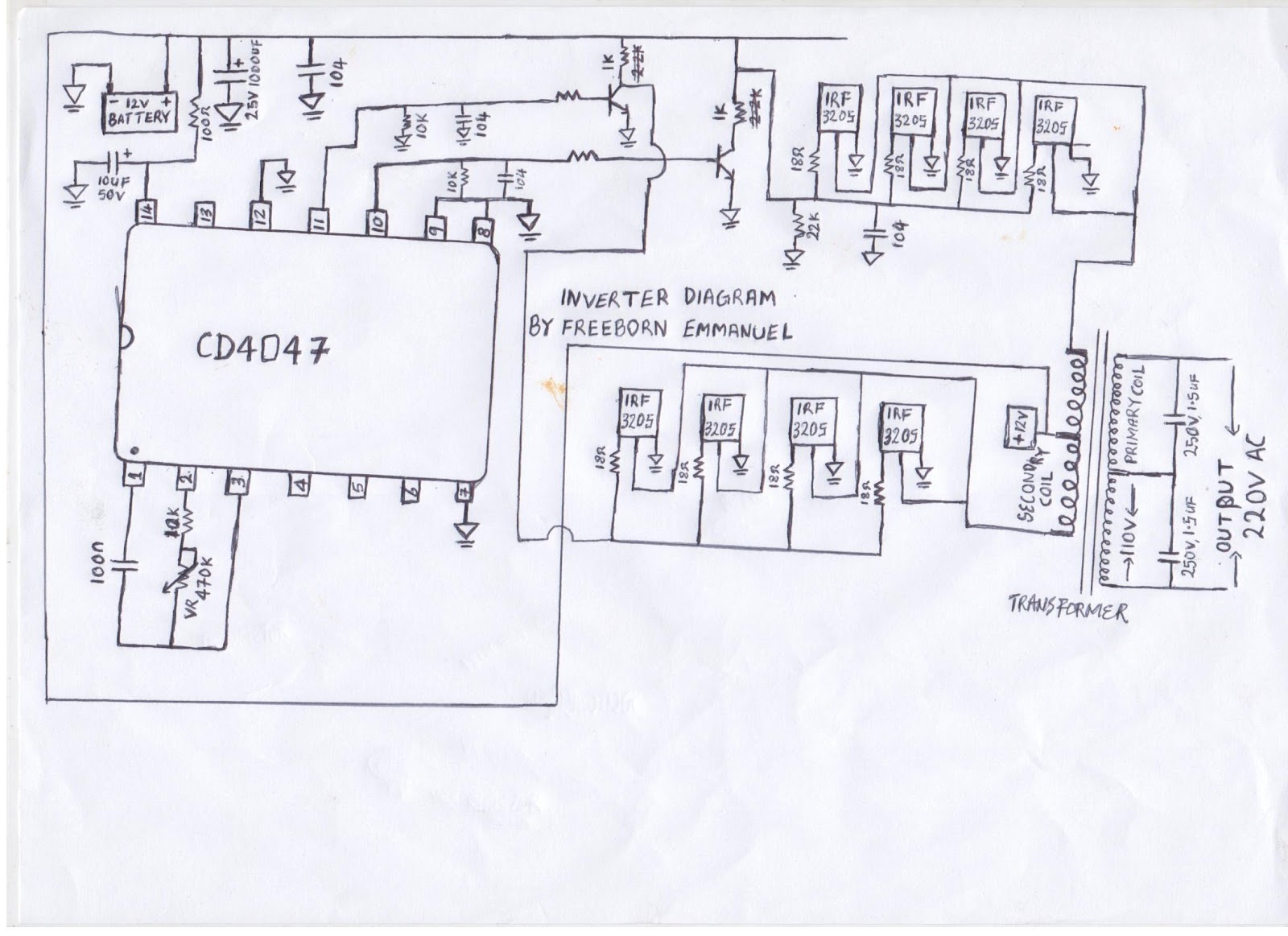
Emmanuel is involved in the design of inverters, battery chargers, automatic changeovers for generators, and stabilizers. He designs locally made inverters for residential and commercial use and installs solar panels alongside inverters. Additionally, he creates solar charge controllers and...
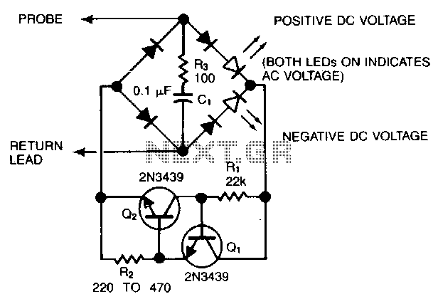
Using inexpensive components, a simple probe circuit can be fitted into a pencil-sized enclosure. When both LEDs are illuminated, the probe indicates the presence of an AC voltage; either LED alone signifies the presence and polarity of a DC...
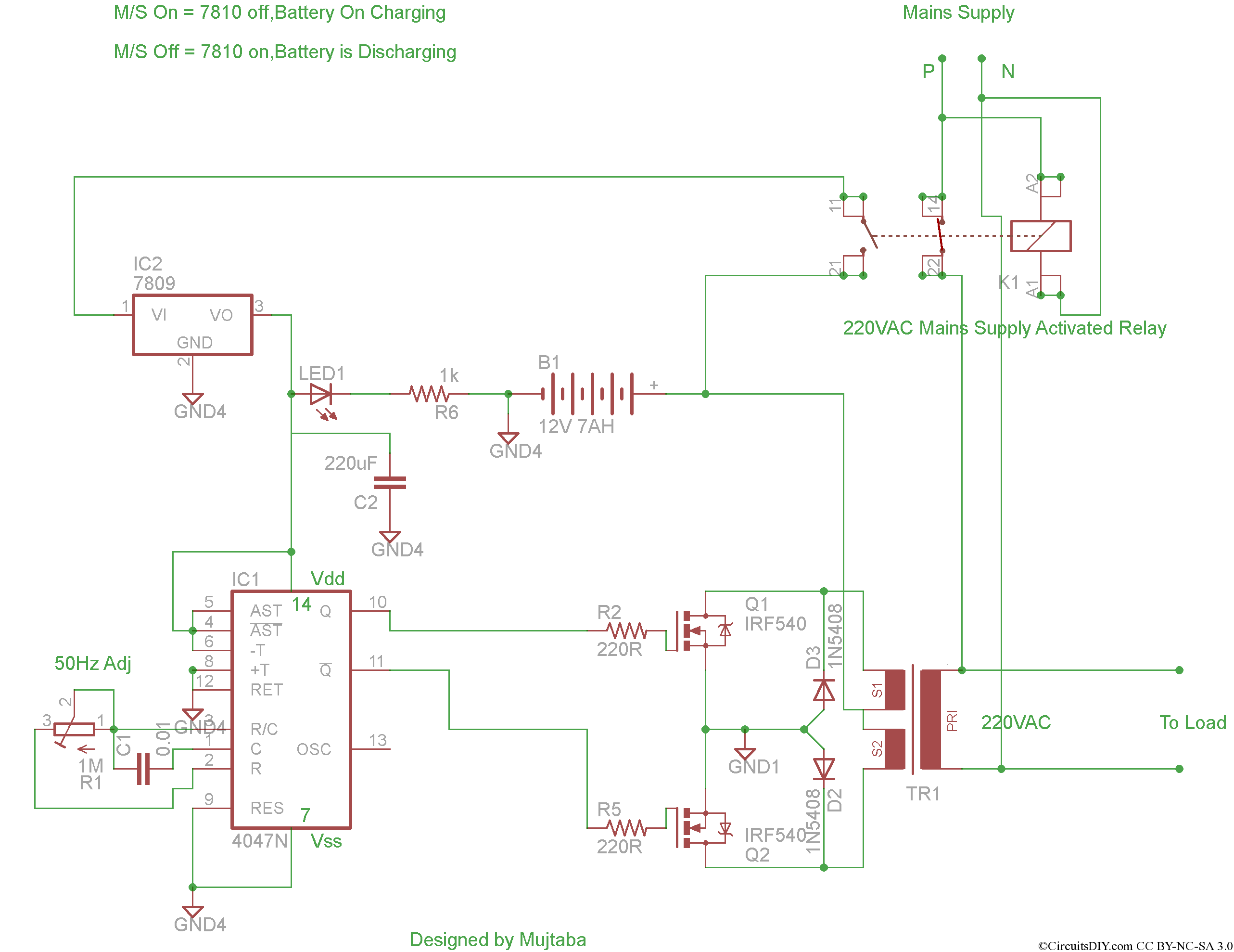
This project involves the development of a complete inverter system that features automatic mains switching, automatic charging when mains power is available, and automatic inverter activation when mains power is lost. The goal is to build a solar inverter...