
220V LED Flasher circuit diagram
The 220V LED flasher circuit operates by controlling the on-off flashing of LED lamps, making it suitable for decorative lighting applications, particularly during festive seasons. The circuit architecture consists of a combination of resistors, capacitors, diodes, and transistors that work in unison to create the desired flashing effect.
The resistors R1, R2, and R4 form a voltage divider and timing circuit with the capacitor C1, which determines the charging and discharging time, thus controlling the frequency of the flashing. The SCR (D5) is triggered by the transistors Q1 and Q2, which are configured in a manner that allows them to switch the SCR on and off based on the timing circuit's output. The choice of transistors, BC327 and BC337, provides sufficient current amplification to effectively drive the SCR.
For optimal performance, the values of C1 and R4 can be selected based on the desired flashing rate. Higher capacitance values lead to slower flashing rates, while lower capacitance values increase the flashing frequency. The circuit's design ensures that it can handle the low current requirements of LED lamps, which allows for the integration of smaller SCRs, thereby enhancing the circuit's overall efficiency and cost-effectiveness.
The inclusion of a female mains socket (SK1) allows for easy connection to the AC power supply, while the diodes (D1-D4) serve as rectifiers to protect the circuit from voltage spikes and reverse polarity, ensuring reliable operation. This LED flasher circuit exemplifies a simple yet effective solution for creating dynamic lighting effects in various applications.This is a 220V LED flasher circuit which is intended as a reliable replacement to thermally-activated switches used for Christmas tree lamp-flashing. This a cheap circuit and easy to build. R1_ 100K R2, R5_ 1K R3, R6_ 470R R4_ 12K C1_ 1000 F 25V D1-D4_ 1N4007 D5_ SCR P0102D Q1_ BC327 Q2_ BC337 SK1_ Female Mains socket The device formed by Q1, Q2 an
d related resistors triggers the SCR. The flashing frequency is provided by R1, R2 and C1. To change flashing frequency value, just set C1 value from 100 to 2200 F, don`t modify R1 and R2. Best performances are obtained with C1=470 or 1000 F and R4=12K or 10K. Due to low consumption of normal 10 or 20 lamp series-loops, very small and cheap SCR devices can be used, e. g. C106D1 or TICP106D. 🔗 External reference
Related Circuits
This simple counter can be utilized to count pulses, serving as the foundation for a customer counter, similar to those found at store entrances, or for any other counting applications. The circuit is compatible with any TTL logic signal...
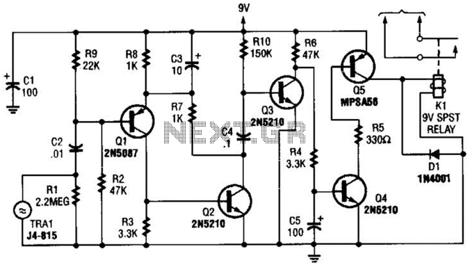
A GC Electronics P/N J4-815 transducer is utilized to receive 40-kHz acoustic remote-control signals. The receiver activates a relay to control another circuit. The GC Electronics P/N J4-815 transducer is designed specifically for the reception of 40-kHz acoustic signals, which...
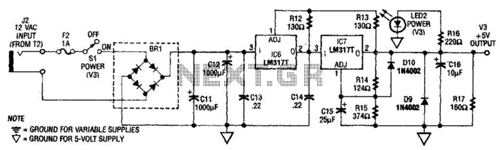
The power supply presented is intended to function with a wall transformer. This circuit can be utilized alongside a variable supply for testing circuits in a laboratory setting. T2 serves as a 12-V wall transformer. The power supply circuit is...
The liquid level controller circuit comprises a power supply circuit and a level detection control circuit, as illustrated in the accompanying chart. The power supply circuit includes a power switch (S1), a power transformer (T), bridge rectifiers (UR1, UR2),...
3V battery-powered circuit that emits a beep after a fixed delay of several minutes. This circuit was created in response to requests from users seeking a timer functionality. The described circuit operates on a 3V power supply, making it suitable...
The current task involves designing the schematic layout, creating the PCB layout, and generating documentation for a contractor with experience in RF schematic design and PCB layout. The block diagram attached should be reviewed. An antenna will connect to...
Warning: include(partials/cookie-banner.php): Failed to open stream: Permission denied in /var/www/html/nextgr/view-circuit.php on line 713
Warning: include(): Failed opening 'partials/cookie-banner.php' for inclusion (include_path='.:/usr/share/php') in /var/www/html/nextgr/view-circuit.php on line 713