
12V to 5V 3A DC converter step down Regulator
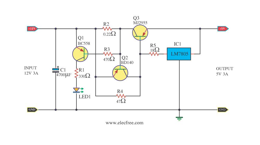
The 12V to 5V DC converter circuit employs a classic linear voltage regulation technique using the 7805 integrated circuit, which is designed for voltage regulation applications. The 7805 provides a stable 5V output with a maximum current of 1A under normal operating conditions, making it suitable for low-power digital circuits. However, to meet the demand for higher current output of up to 3A, the circuit incorporates the MJ2955 transistor as a current amplifier.
The configuration involves connecting the output of the 7805 to the base of the MJ2955, allowing it to function as a pass transistor. When the load requires more than 1A, the MJ2955 takes over, providing the additional current needed while the 7805 maintains the voltage regulation. This configuration ensures that the 7805 operates within its safe limits while allowing the circuit to deliver the required 5V at 3A.
To enhance the protection of the circuit, an LED (LED1) is included as an overload indicator. In the event of a short circuit or excessive load, the LED lights up, alerting the user to the issue. Additionally, the BD140 transistor (Q2) is employed as a protective switch. When the overload condition is detected, Q2 is activated, which in turn turns off the MJ2955 (Q3), effectively shutting down the output and preventing damage to the circuit components.
The overall design of the circuit is straightforward, utilizing readily available electronic components, making it accessible for hobbyists and professionals alike. The simplicity of the circuit layout and the use of common parts contribute to its popularity in various applications where a reliable 5V power supply is needed from a 12V source. This design not only meets the current requirements but also ensures safety and ease of assembly, making it an excellent choice for powering digital circuits.Today I has 12V to 5V 3A DC converter step down Regulator circuit come to deposit. In sometimes friends have power supply 12V 3A, but want Voltage 5V 3A for digital Circuit. This circuit can meet the demand of friends get, by it uses normal electronic part and have 7805 integrated circuits perform to control Voltage 5V Regulate alone it gives cu rrent get just 1A. then must have an assistant is transistor MJ2955 perform enlarge current tallly go up be 3A besides. When be born over load or shot circuit as a result still have LED1 bright warn with. And still make Q2 BD140 work cause Q3 MJ2955 stop work with. The circuit then safe have no a problem friends may like this circuit. Because the equipment seeks easy, build not difficult too yes. 🔗 External reference
Related Circuits
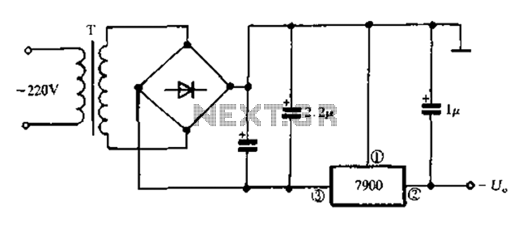
7900 series three-terminal fixed negative output voltage regulator circuit The 7900 series comprises a range of three-terminal fixed negative voltage regulators designed to provide stable output voltages. These regulators are specifically engineered to deliver a consistent output voltage, which is...
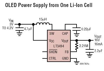
The LT3494 and LT3494A are low-noise boost converters that integrate a power switch, Schottky diode, and output disconnect circuitry. These devices utilize an innovative control technique that results in minimal output voltage ripple and high efficiency across a broad...
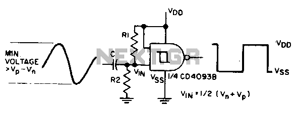
The sine input is AC coupled by capacitor C. Resistors Rl and R2 bias the input midway between Vn and Vp, which are the input threshold voltages. This configuration is designed to provide a square wave at the output. The...
This project is a cost-effective solution for operating 20 or 40-watt fluorescent tubes. The most efficient configuration utilizes a 40-watt tube or two 20-watt tubes connected in series. The circuit can be assembled using components sourced from a junk...
This application note details the design of a 50-watt, isolated, forward converter, utilizing the MAX8540 synchronizable, high-frequency, current-mode PWM controller. The schematic design of the 50-watt isolated forward converter using the MAX8540 involves several key components and stages to ensure...
This is a very sensitive 50Mc converter allowing you to receive the entire "Magic Band" (50Mc...52Mc) on your general coverage receiver (28Mc...30Mc). It receives all types of modulated transmissions. It all depends on the receiver used. I’ve tested this...
Warning: include(partials/cookie-banner.php): Failed to open stream: Permission denied in /var/www/html/nextgr/view-circuit.php on line 713
Warning: include(): Failed opening 'partials/cookie-banner.php' for inclusion (include_path='.:/usr/share/php') in /var/www/html/nextgr/view-circuit.php on line 713