
7900 series three-terminal fixed negative output voltage regulator circuit
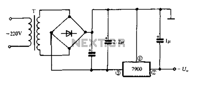
The 7900 series comprises a range of three-terminal fixed negative voltage regulators designed to provide stable output voltages. These regulators are specifically engineered to deliver a consistent output voltage, which is pivotal in various electronic applications requiring reliable power supply management.
The typical configuration of a 7900 series regulator includes three pins: input, output, and ground. The input pin connects to the unregulated negative voltage source, while the output pin delivers a regulated negative voltage to the load. The ground pin serves as a reference point for the output voltage.
Common output voltages available in the 7900 series include -5V, -12V, and -15V, making them suitable for various electronic circuits that require negative voltage supplies. The devices are designed to handle input voltages up to -35V, ensuring compatibility with a range of power sources.
The internal architecture of the 7900 series regulators typically includes a thermal shutdown feature, short-circuit protection, and a safe operating area, which collectively enhance the reliability and safety of the circuit. Additionally, these regulators can provide output currents up to 1A, depending on the specific model, making them versatile for different load requirements.
To utilize a 7900 series regulator in a circuit, it is essential to connect appropriate input and output capacitors to stabilize the voltage and improve transient response. A typical application circuit may include an input capacitor (e.g., 0.33 µF) placed close to the input pin and an output capacitor (e.g., 0.1 µF) near the output pin. This configuration minimizes voltage fluctuations and enhances performance under varying load conditions.
In summary, the 7900 series three-terminal fixed negative voltage regulators are integral components in power management systems, providing reliable and stable negative voltage outputs for a variety of electronic applications. Their robust design and ease of integration make them a popular choice among engineers and designers in the field of electronics.7900 series three-terminal fixed negative output voltage regulator circuit
Related Circuits
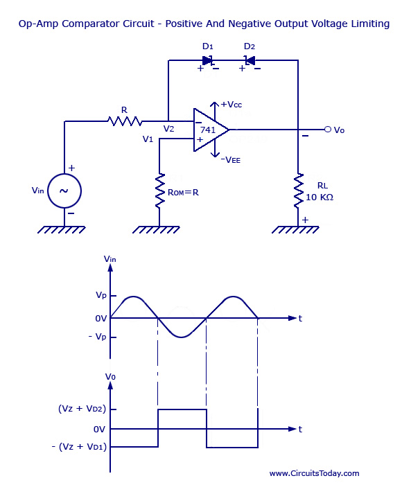
Voltage Limiter Circuit Using Op-amp - Circuit Diagram, Waveform, Positive and Negative Voltage Limiters. The voltage limiter circuit utilizing an operational amplifier (op-amp) serves to restrict the output voltage to predefined levels, effectively preventing it from exceeding or falling below...
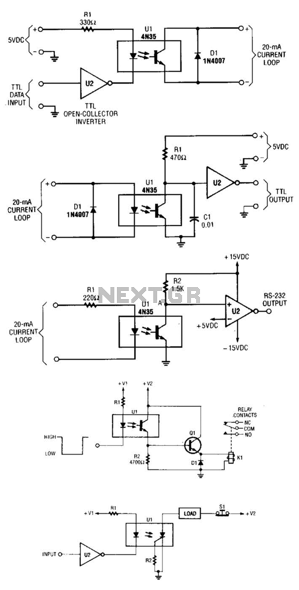
A circuit for isolating a variable resistor is presented. An optoisolator, which consists of an LED and a photo-conductive cell (or photoresistor), is utilized. The current flowing through the LED regulates its brightness, which subsequently dictates the resistance between...
The game-scoring display screen circuit diagram is depicted in the image above. The circuit consists of an add/subtract scoring input circuit, an add/subtract scoring circuit, a counting-decoding display circuit, and a reset circuit. The game-scoring display circuit is designed to...
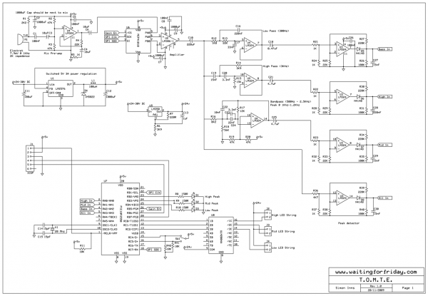
Most existing designs utilize direct switching of lights without any software control and include manual potentiometers for light sensitivity and overall gain settings. There are limited references regarding the frequency filter circuitry, explaining the specific frequencies the circuit is...
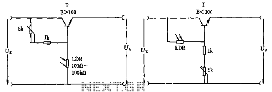
The circuit depicted involves a photoresistor (LDR) connected to a transistor, which operates at either a high or low level based on light conditions. The amplification factor of the transistor is 100, which is adequate for the application. The...
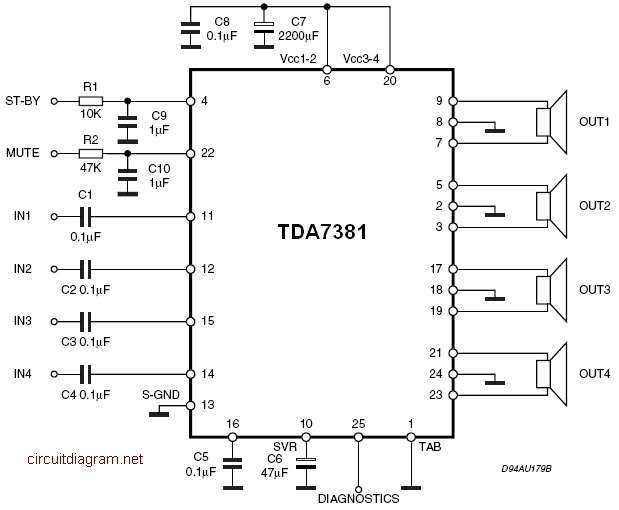
The TDA7381 is a Class AB audio power amplifier housed in a Flexiwatt25 package, specifically intended for car radio applications. This circuit can also be utilized for various other purposes. The fully complementary PNP/NPN output configuration enables a rail-to-rail...