
Sine wave-to-square wave converter
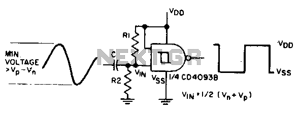
The circuit utilizes an AC coupling technique through capacitor C, which allows only the alternating current (AC) component of the input signal to pass while blocking any direct current (DC) offset. This is crucial in applications where the input signal may have a DC component that could affect the performance of subsequent stages in the circuit.
Resistors Rl and R2 are configured to set the bias point of the input signal. By positioning the bias point between Vn (the negative threshold voltage) and Vp (the positive threshold voltage), the circuit ensures that the input signal oscillates around a midpoint that facilitates the desired output waveform. This midpoint biasing is essential for achieving optimal signal processing, as it allows the signal to swing fully between the thresholds without clipping.
The output of the circuit is designed to generate a square wave. This is typically achieved through the use of a comparator or a Schmitt trigger configuration. The square wave output is characterized by rapid transitions between high and low states, making it suitable for applications such as digital signal processing, timing circuits, or clock generation.
In summary, the combination of AC coupling through capacitor C and the biasing arrangement of resistors Rl and R2 enables the circuit to effectively convert a sine wave input into a square wave output, ensuring proper signal integrity and performance for subsequent electronic stages.The sine input is ac coupled by capacitor C; Rl and R2 bias the input midway between Vn and Vp, the input threshold voltages to provide a square wave at the output. 🔗 External reference
Related Circuits
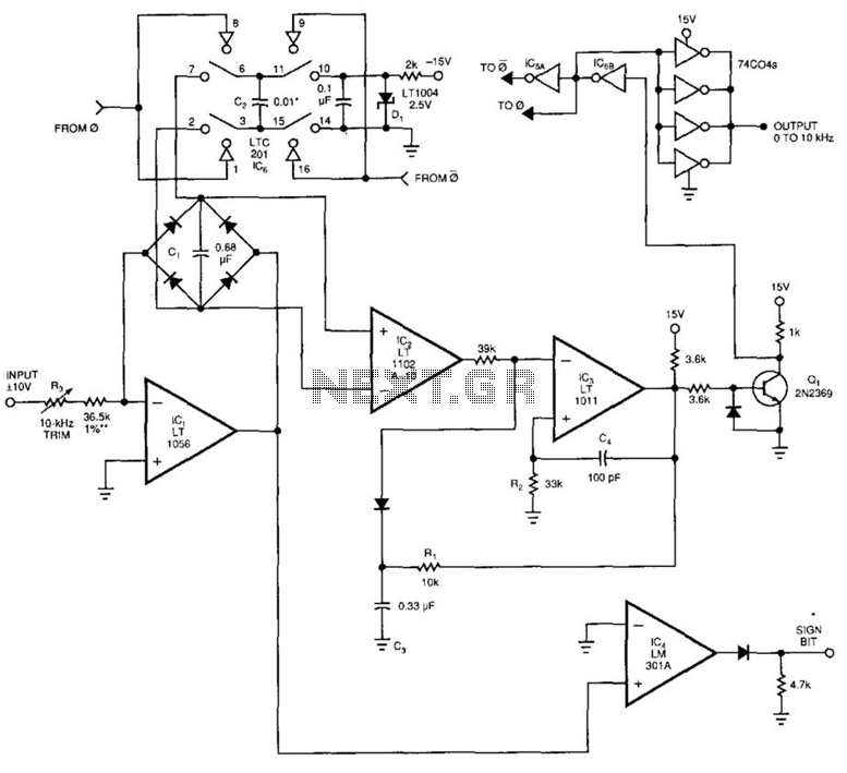
This voltage-to-frequency converter (VFC) accepts bipolar AC inputs. For -10 to +10 V inputs, the converter produces a proportional 0 to 10 kHz output. Linearity is 0.04%, and the temperature coefficient (TC) is approximately 50 ppm/°C. To understand the...
This circuit is an RMS-calibrated AC voltmeter that provides average readings. Removing capacitor C2 eliminates the averaging function, resulting in a precision full-wave rectifier, while removing capacitor C1 transforms the circuit into an absolute value generator. The operation of...
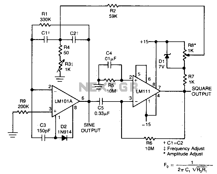
This circuit will provide both a sine and square wave output for frequencies ranging from below 20 Hz to above 20 kHz. The frequency of oscillation can be easily adjusted by changing a single resistor. This circuit is designed to...
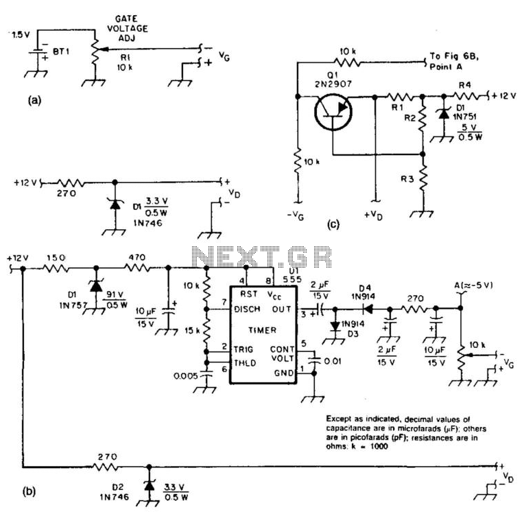
These two circuits provide bias for the microwave preamplifiers discussed in this text. The circuit in Figure 51-5(a) is a simple passive power supply. Figures 51-5(b) and 51-5(c) represent active power supplies, with Ul generating a negative supply and...
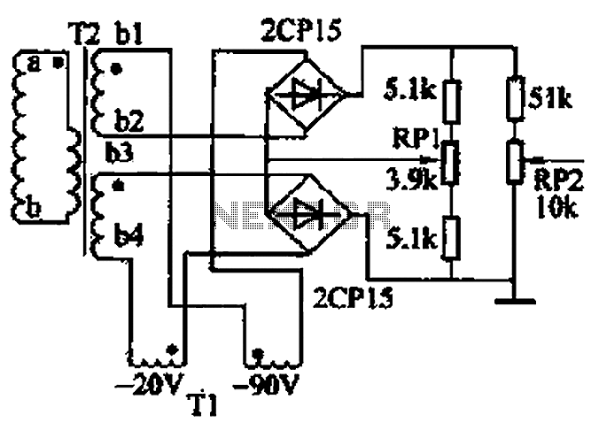
The closed-loop system consists of longitudinal and transverse components. The circuit operates as follows: a control circuit from the stepping motor CNC system issues a command, which the receiver detects. This signal is processed through a phase-sensitive rectifier to...
This circuit utilizes a PIC microcontroller and an internal 1 kHz sinewave table to generate an accurate sinewave. It requires only a few external components for filtering. The sinewave benefits from high frequency accuracy due to its generation from...
Warning: include(partials/cookie-banner.php): Failed to open stream: Permission denied in /var/www/html/nextgr/view-circuit.php on line 713
Warning: include(): Failed opening 'partials/cookie-banner.php' for inclusion (include_path='.:/usr/share/php') in /var/www/html/nextgr/view-circuit.php on line 713