
12vdc 220vac inverter
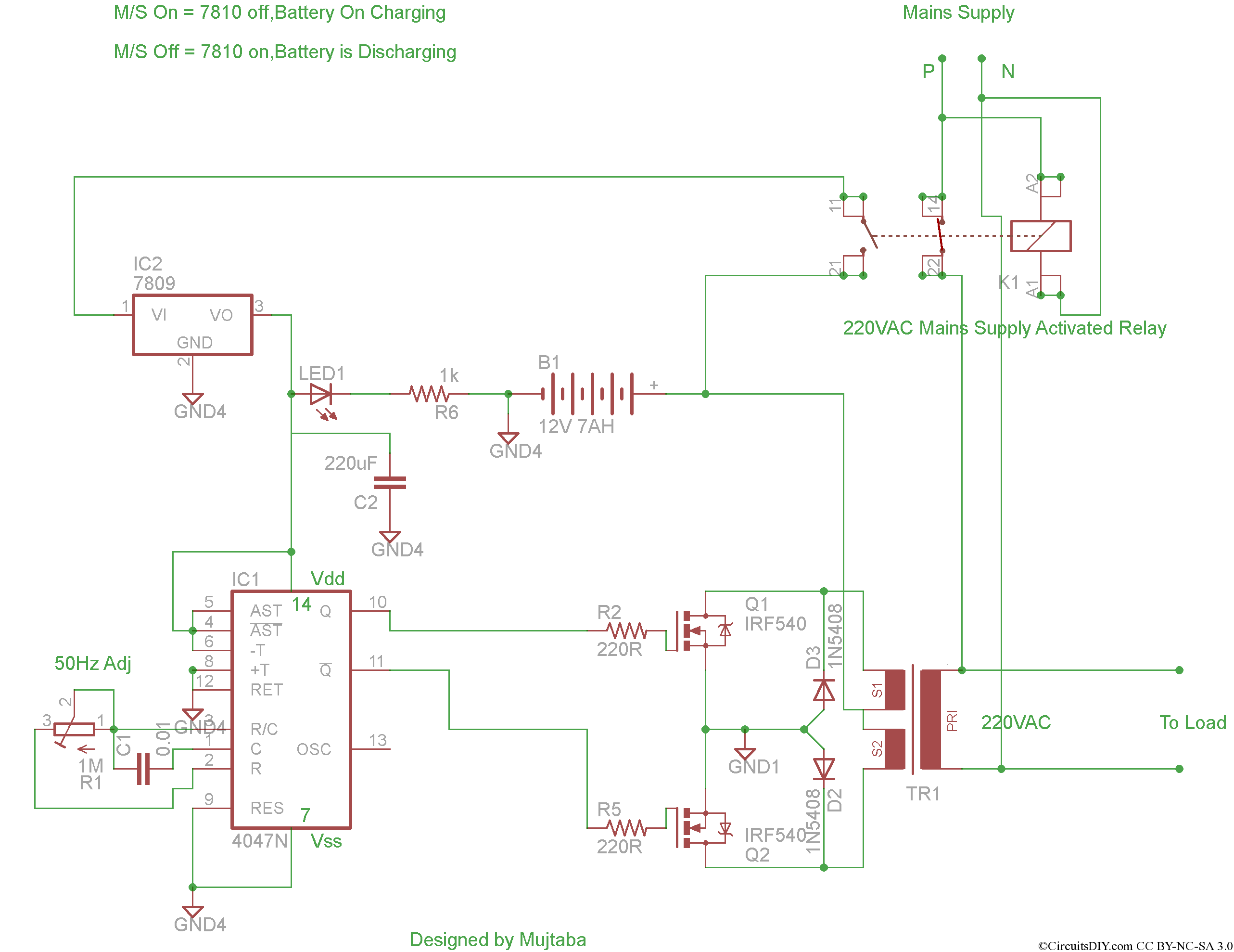
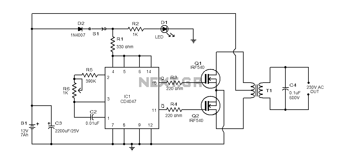
The inverter circuit utilizes the CMOS 4047 as a primary oscillator, generating a square wave signal that is essential for the conversion of DC to AC. The astable multivibrator configuration allows for continuous oscillation, producing a frequency determined by external resistors and capacitors connected to the 4047. The output from the 4047 is a symmetrical square wave, which is then amplified by the Darlington pair transistors (T1 and T2). This amplification stage is crucial as it increases the current capacity of the signal to drive the transformer effectively.
The transformer plays a vital role in the voltage conversion process. With a primary winding designed for 220V AC, the transformer steps up the voltage from the amplified signal to the desired output level. A toroidal core is recommended due to its efficiency and reduced electromagnetic interference, which enhances the overall performance of the inverter.
The output frequency of the inverter can be finely tuned using potentiometer P1, allowing the user to adjust it between 50 Hz and 400 Hz. This flexibility is beneficial for different applications, ensuring compatibility with various electronic devices that may require specific frequency inputs.
Overall, this inverter circuit provides a practical solution for converting low-voltage DC power into usable AC power, making it suitable for a range of small electronic devices in home energy applications. Proper attention to component selection and circuit design will optimize the inverter's performance and reliability.This circuit inverter converts 12V DC battery to AC 22oV as the replacement of home energy. The inverter can be used for small electronic devices such as lamps, radio, phone charger, disc player, etc. The inverter circuit is a central component, the CMOS 4047, and converts a DC voltage of 12 V to 220 V AC voltage.
4047 is used as an astable multiv ibrator. The pin 10 and 11 we find a symmetrical rectangular signal is amplified by Darlington transistors T1 and T2 trailer, and finally reaches the secondary coil of a transformer of the network (2 x 10V/100VA). Primary coil voltage is 220 AC voltage terminals. For best performance, use a toroidal core transformer with low losses. P1 to the output frequency can be regulated within certain limits (50. 400 Hz). 🔗 External reference
Related Circuits
This is a straightforward tester designed to verify the fundamental operations of an infrared remote control unit. It is cost-effective and simple to assemble. The tester utilizes the infrared receiver module TSOP1738. The operation of the remote control is...
This is a simple high-voltage inverter circuit. It uses an NPN transistor type 2N3055. This circuit is designed to invert low voltage to high voltage. The high-voltage inverter circuit utilizing the 2N3055 NPN transistor serves as an effective means to...
This project involves the development of a complete inverter system that features automatic mains switching, automatic charging when mains power is available, and automatic inverter activation when mains power is lost. The goal is to build a solar inverter...
The inverter is designed for powering mains appliances using battery sources. It functions as a switching converter, eliminating the need for bulky, heavy, and costly iron transformers. This design provides advantages such as compact size, lightweight construction, precise output...
This document provides an explanation of a simple 100-watt inverter circuit using the IC CD4047 and the IRF540 MOSFET. The circuit is designed to be simple, cost-effective, and suitable for assembly on a veroboard. The CD4047 is a low-power...
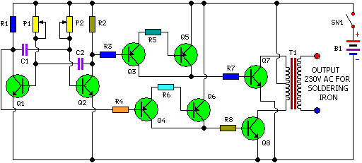
This is a simple and cost-effective inverter designed for small soldering irons (25W, 35W, etc.) to be used in the absence of mains supply. The circuit employs eight transistors along with a few resistors and capacitors. Transistors Q1 and...