
Small wattage Inverter (Inverter Circuit For Soldering Iron)
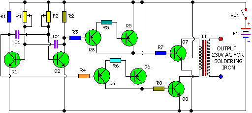
The inverter circuit operates by converting a 12V DC supply from the battery into a 230V AC output suitable for powering small soldering irons. The astable multivibrator configuration formed by transistors Q1 and Q2 generates a square wave output at a frequency of 50Hz, which is essential for the operation of the soldering iron. The use of Darlington pairs Q3-Q5 and Q4-Q6 enhances the current gain, allowing the circuit to drive larger currents necessary for the power transistors Q7 and Q8.
Transistors Q7 and Q8, being 2N3055, are robust power transistors capable of handling high current loads. Their push-pull configuration enables efficient operation, minimizing distortion in the output waveform. The inclusion of heat sinks for these transistors is critical, as they will dissipate significant heat during operation, ensuring reliability and longevity of the components.
The transformer T1 plays a vital role in the circuit, stepping down the voltage to a safe level while providing the necessary current. The center-tapped configuration of the secondary winding allows for easy connection to the battery and facilitates the alternating current output needed for the soldering iron.
When assembling the circuit, careful attention should be paid to the layout on the PCB to minimize noise and interference. Proper gauge wires should be used for connections to handle the current without overheating. The selection of the battery must also align with the expected load to ensure adequate performance and operational time.
Finally, the user interface, including the power switch and the socket for the soldering iron, should be designed for safety and ease of use, ensuring that the inverter can be operated without risk of electrical hazards. Overall, this inverter design provides a practical solution for operating small soldering irons in environments where mains power is unavailable.Here is a simple but inexpensive inverter for a small soldering iron (25W, 35W, etc) In the absence of mains supply. It uses eight transistors and a few resistors and capacitors. Transistors Q1 and Q2 (each BC547) form an astable multivibrator that produces 50Hz signal. The complementary outputs from the collectors of transistors Q1 and Q2 are fed to pnp Darlington driver stages formed by transistor pairs Q3-Q5 and Q4-Q6 (utilising BC558 and BD140). The outputs from the drivers are fed to transistors Q7 and Q8 (each 2N3055) connected for push-pull operation.
Use suitable heat-sinks for transistors Q5 through Q8. A 230V AC primary to 12V-0-12V, 4. 5A secondary transformer (T1) is used. The centre-tapped terminal of the secondary of the transformer is connected to the battery (12V, 7Ah), while the other two terminals of the secondary are connected to the collectors of power transistors T7 and T8, respectively. When you power the circuit using switch S1, transformer X1 produces 230V AC at its primary terminal. This voltage can be used to heat your soldering iron. Assemble the circuit on a generalpurpose PCB and house in a suitable cabinet. Connect the battery and transformer with suitable current-carrying wires. On the front panel of the box, fit power switch S1 and a 3-pin socket for connecting the soldering iron.
Note that the ratings of the battery, transistors T7 and T8, and transformer may vary as these all depend on the load (soldering iron). 🔗 External reference
Related Circuits
The circuit is designed to operate with an audio power amplifier that uses 18V-0V-18V power rails. The specific voltage is not critical, but the feedback is referenced to an LED chain connected to a 12V rail, necessitating a separate...
This infrared (IR) remote extender enhances the range of most basic IR remotes operating at a 40KHz modulation frequency significantly. When in operation, the remote is aimed at the detector on the circuit, and a button is pressed. The...
Powered by a solar panel, the circuit provides a 5V pure regulated DC voltage. It consists of an oscillator transistor and a regulator transistor. The solar panel charges the battery when sunlight is sufficient to generate a voltage above...

The circuit utilizes a transistor (VT) and a voltage regulator (VSL) to create a constant current source, employing three regulators to enhance the performance of the regulator circuit. The described circuit employs a transistor (VT) in conjunction with a voltage...
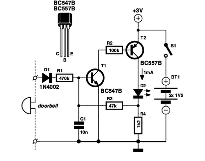
If you are expecting an important visitor but need to step out for a moment, an electronic doorbell memory can be useful to check who rang the bell. An electronic doorbell memory system is designed to capture and store the...
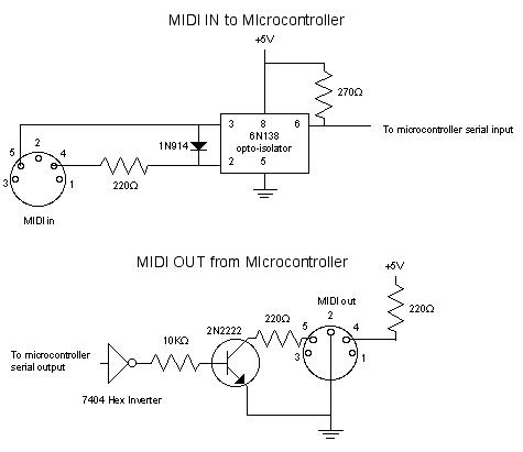
MIDI, or Musical Instrument Digital Interface, is a specification for a communications protocol between digital synthesizers and other digital music devices. It was developed to be as simple and general as possible, providing synthesizer manufacturers with significant flexibility while...