
High Voltage Inverter
The high-voltage inverter circuit utilizing the 2N3055 NPN transistor serves as an effective means to convert low DC voltage into a higher AC voltage. The 2N3055 is a well-known power transistor capable of handling high current and voltage levels, making it suitable for this application.
The circuit typically consists of a few key components: the 2N3055 transistor, a transformer, resistors, and capacitors. The input low voltage is applied to the base of the 2N3055 transistor through a resistor, which controls the base current and thus the operation of the transistor. When the base current flows, the transistor turns on, allowing current to flow from the collector to the emitter, which is connected to one side of the transformer.
The transformer plays a crucial role in the circuit by stepping up the voltage. The low voltage from the transistor is fed into the primary winding of the transformer. The turns ratio of the transformer determines the increase in voltage. The secondary winding then produces a higher AC voltage output.
Capacitors may be included in the circuit to filter out noise and stabilize the voltage levels. Additionally, feedback mechanisms can be implemented to regulate the output voltage and improve efficiency. The circuit design must ensure that the components are rated for the high voltage levels generated to prevent damage and ensure safety.
Overall, this high-voltage inverter circuit is a practical solution for applications requiring the conversion of low voltage DC sources into higher voltage AC outputs, suitable for powering various devices or systems that operate at elevated voltage levels. Proper design considerations, including component selection and circuit layout, are critical for optimal performance and reliability.This is a simple high voltage inverter circuit. It is uses NPN transistor type 2N3055. This circuit used to invert low voltage to high voltage. Besides that,.. 🔗 External reference
Related Circuits
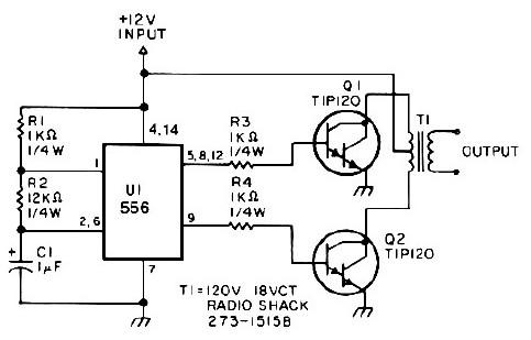
This low-power 25-watt power inverter circuit utilizes only nine electronic components. The inverter converts a DC input voltage ranging from 10V to 16V into a 60Hz, 115V square-wave power output, capable of powering AC electronic devices up to approximately...
This circuit is based on the State Variable Band Pass Filter, incorporating amplitude-limited regenerative feedback. The State Variable Band Pass Filter (SVBPF) is a versatile filter design that allows for simultaneous control over the center frequency, bandwidth, and gain. This...
A 40-watt fluorescent tube lamp or two 20-watt tubes in series will be driven by this circuit. The transformer is wound on a ferrite rod with a diameter of 10 mm and a length of 8 cm. The circuit described...
Q1 and Q2, along with T1, determine the wattage output of the inverter. Using Q1 and Q2 as 2N3055 transistors and T1 rated at 15 A, the inverter can provide approximately 300 watts. Substituting larger transformers and more powerful...
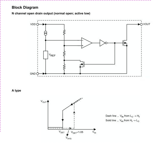
The HT70XX series comprises a collection of three-terminal low-power voltage detectors constructed using CMOS technology. Each voltage detector within the series is designed to detect a specific fixed voltage within the range of 2.2V to 7V. These detectors feature...
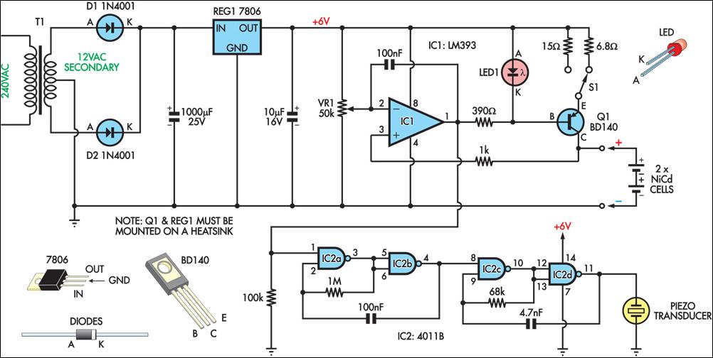
This circuit charges two NiCad cells with a constant current and features dual charging rates, voltage cutoff, and an audible alarm. The circuit is powered by a 12VAC center-tapped mains transformer, along with two rectifier diodes (D1 & D2)...