
12VDC to 230VAC 60W Inverter Circuit
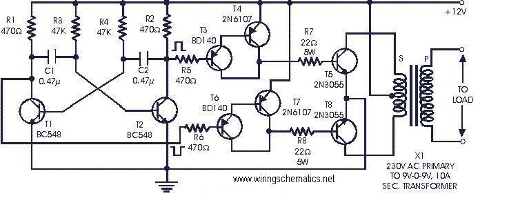
The described inverter circuit employs a multivibrator configuration using two BC548 transistors (T1 and T2) to generate a square wave signal at a frequency of 50Hz. This frequency is crucial for the inverter's operation, and the resistors R3 and R4 play a significant role in determining the oscillation frequency. After initial testing, these resistor values may need to be fine-tuned to ensure optimal performance.
The output from the collectors of T1 and T2 is fed into two Darlington pairs formed by transistors T3-T4 and T6-T7, which are BD140 and 2N6107, respectively. The Darlington configuration provides high current gain, which is essential for driving the larger power transistors (T5 and T8). The 2N3055 transistors are configured in a push-pull arrangement, allowing the inverter to efficiently convert the DC voltage from the battery to an AC output suitable for driving loads.
To enhance the output capability of the inverter, the drive to the 2N3055 transistors can be increased. This can be achieved by lowering the resistance values of R7 and R8, which would allow more base current to flow into T5 and T8. However, it is important to ensure that these resistors can handle the increased power dissipation, necessitating the use of higher wattage ratings.
Thermal management is a critical aspect of the design, as the output transistors can generate significant heat during operation. Therefore, suitable heat sinks should be attached to the 2N3055 transistors to maintain their operating temperature within safe limits, thus preventing thermal runaway and ensuring reliability.
The transformer (X1) is a key component, with a primary winding rated for 230V and a secondary winding of 9V-0-9V at 10A. This transformer is used in reverse to step up the voltage from the inverter's output to the desired AC voltage level. The design effectively utilizes the transformer to provide isolation and voltage transformation, making it suitable for various applications where a stable AC supply is required from a DC source. Overall, this inverter circuit presents a practical solution for powering medium loads efficiently and economically.The following circuit is a cheap completely transistorised inverter circuit ideal for driving medium loads with the order of 40 to 60 watts working with battery of 12V, 15 Ah or larger power capacity. Transistors T1 and T2 (BC548) make a 50Hz multivibrator. For having right frequency, the values of resistors R3 and R4 might need to be modified aft er testing. The complementary outputs from Collectors of transistors T1 and T2 are provided to PNP darlington driver phases created by transistor pairs T3-T4 and T6-T7 (utilising transistors BD140 and 2N6107). The outputs from the drivers are fed to transistors T5 and T8 (2N3055) connected for push-pull operation.
Somewhat bigger wattage can be accomplished by growing the drive to 2N3055 transistors (by lowering the value of resistors R7 and R8 while raising their wattage). Suitable heatsinks may be applied for the output stage transistors to keep the transistor from overheating.
Transformer X1 is really a 230V primary to 9V-0-9V, 10A secondary used in reverse. 🔗 External reference
Related Circuits
Due to the varying conditions of different input signals, when an abnormal voltage is applied to the pin, protection circuits are established to create a circuit path from the LSI (large scale integration) circuits for internal protection. The structure...
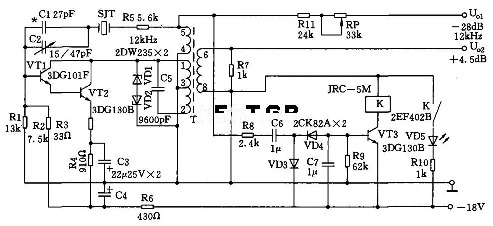
The circuit depicted is a 12 kHz intermediate frequency oscillator designed for an alarm system. It employs a variable feedback oscillation circuit where the oscillation frequency is primarily determined by a quartz crystal. Capacitors C1 and C2 are used...
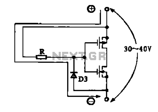
This circuit is designed to drive a total of 42 LEDs, assuming a forward voltage of approximately 2.2V per LED and a forward current of around 21mA for adequate brightness. If the specifications of the LEDs differ significantly, modifications...
This schematic illustrates an infrared (IR) transmitter circuit utilizing an integrated circuit (IC). The circuit employs the widely recognized NE555 timer IC, which operates as an astable multivibrator to generate a signal with a frequency of 38 kHz. The...
This page features basic, visible light photo-detector circuits that can be used to detect trains. These methods would normally be used with the photo sensor mounted between the rails. The described photo-detector circuits are designed to detect the presence of...
This is a simple electronic siren circuit that can be utilized in various applications where a siren sound is necessary. The circuit is straightforward, employing only two transistors and a few additional components, and it will produce a siren...