
13 GHz Frequency Counter Prescaler
This circuit serves as a valuable tool for amateur radio enthusiasts and professionals seeking to enhance the capabilities of older frequency counters. The integration of high-frequency prescalers and digital logic components allows for precise frequency measurements in the microwave range, extending the utility of budget-friendly equipment. The careful selection of components, along with adherence to proper construction practices, ensures reliable performance and accuracy in frequency division applications. The design exemplifies the innovative spirit of the amateur radio community, providing an accessible solution for those looking to expand their measurement capabilities without the need for expensive, high-end frequency counters.A fairly simple "divide-by-1000" circuit which was first designed by Zeljko Bozic, S52ZB, in a 2006 issue of VHF Communications Magazine. The idea of this project is to extend the range of older (and cheaper) frequency counters. You can often find 100 MHz frequency counters for as little as $20 at hamfests or eBay, and this simple circuit wi
ll extend their range up to at least 13 GHz. This version is based around a Hittite HMC363 divide-by-8 prescaler, a Fujitsu MB506 divide-by-64 prescaler, and a "divide-by-1. 953125" circuit using standard digital logic. The Hittite HMC363 front-end prescaler is good up to 13 GHz or so, and will do 15 GHz if you increase the input RF power a bit and minimize the prescaler`s exposure time.
It`s possible to pick up the Hittite HMC363 evaluation board for around $100, or you may be able to receive a couple HMC363s as free samples. The evaluation board will be ideal, as it`s properly designed for high-frequency microwave work. The Fujitsu MB506 can be found in some MMDS or satellite TV downconverters, the Fujitsu MB501 can probably be substituted with a slight circuit change.
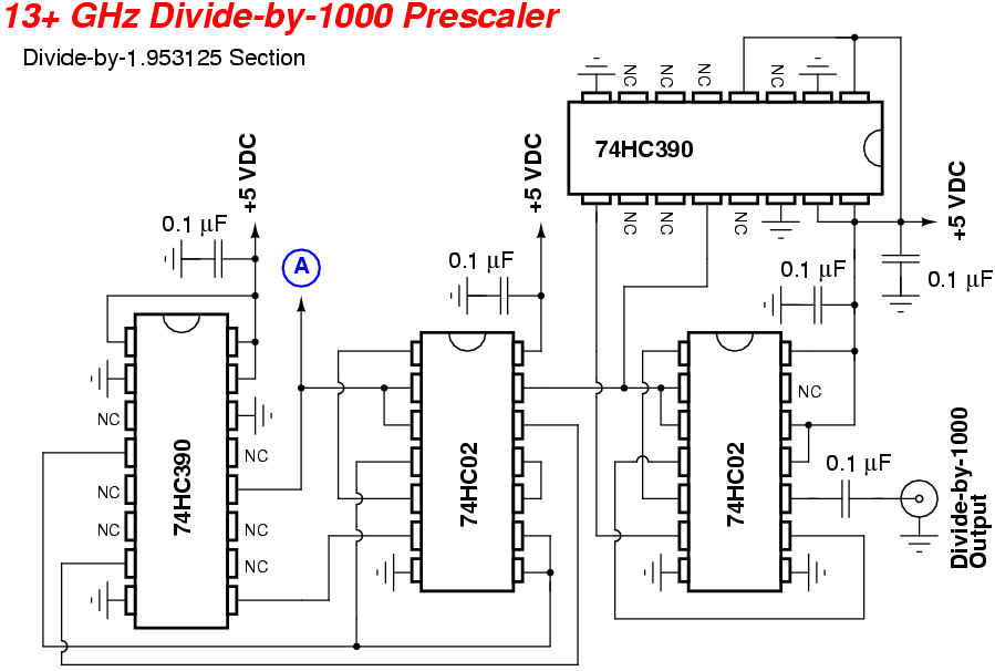
Fujitsu MB501 prescalers can be found in older analog cellular phones. The rest of the circuit is just a simple ECL-to-CMOS logic converter using a Maxim MAX961 high-speed comparator, and some 74HC390 ripple-counters and 74HC02 NOR-gate logic chips wired up as a divider. The output of the Fujitsu MB506 is in Emitter-Coupled Logic (ECL), which means the signal is 1. 6 volts peak-to-peak with a DC offset of around 3 volts. The Maxim MAX961 compares this signal to a preset reference DC voltage and converts the signal into one with the normal +5/0 volts that we`re used to.
The "divide-by-1. 953125" circuit is based around the fact that by using three "divide-by-1. 25" circuits you can effectivly divide by 1. 953125 (1. 25 x 1. 25 x 1. 25 = 1. 953125). Dividing by non-whole numbers comes about by removing certain pulses in the divider chain. The Hittite HMC363 evaluation board is in the middle, an old California Amplifier downconverter case (upper-right) will hold the rest of the digital logic. Panel-mount N and BNC connectors will be for the RF input and prescaler output. The circuit will be powered via eight "AA" batteries (+12 VDC) in a standard holder available at Radio Shack.
The +12 VDC comes in to the 78L05 voltage regulator via the 1000 pF feed-through capacitor on the upper-left. The other feed-through capacitor provides a clean +5 VDC source to supply the Hittite HMC363 evaluation board.
In the middle-left, is the Fujitsu MB506 prescaler fed via a BNC jack attached to the downconverter case. The 8-pin SMT part to the lower-right of the MB506 is the Maxim MAX961 comparator. On the right-side are the two 74HC390 ripple-counters and 74HC02 two-input NOR gates. The maximum input to the Fujitsu MB506 prescaler will be around 1. 6 GHz, so proper microwave construction techniques will need to be used for that IC. Everything else can be handled as regular low-frequency signals. High-quality conformable coax is used on the HMC363`s RF input due to its better support for frequencies above 10 GHz.
The rest of the RF cables can be standard RG-58, or equivalent, as they will be carrying lower frequency signals. Do try to use high-quality coax and connectors throughout this project to avoid signal leakage or receiving external RF signals.
The frequency counter is reading "10. 51124 MHz" for a final RF input frequency of 10. 51124 GHz. This signal was a Gunn diode source from a stock MPH Industries K55 X-band police radar with a WR-90 to N adapter. The output from this Gunn diode source is around +14 dBm (25 mW), so a 10 dB attenuator was added to the input of the prescaler to knock the signal down a bit.
🔗 External reference
Related Circuits
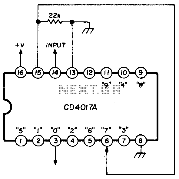
A single connection change allows division by any integer between 2 and 10. The RCA CD4017A Johnson decade counter is configured as a divide-by-7 counter. A resistor is utilized to maintain the reset line in a low state. When...
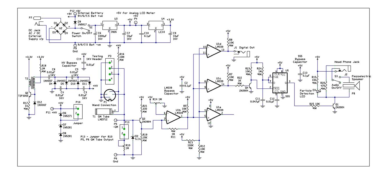
With the recent events at the Fukushima Dai-ichi nuclear power plant, it would be interesting to build a Geiger Counter and connect it to a NerdKit for interfacing with a computer. An article detailing the building process is available,...
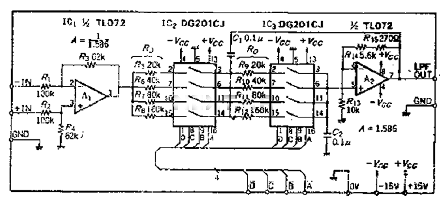
The circuit primarily consists of two Butterworth filters, designed to create a feedback amplifier with a gain of approximately 0.707. It features a differential input amplifier, where one input is grounded, resulting in a single input terminal. The attenuation...
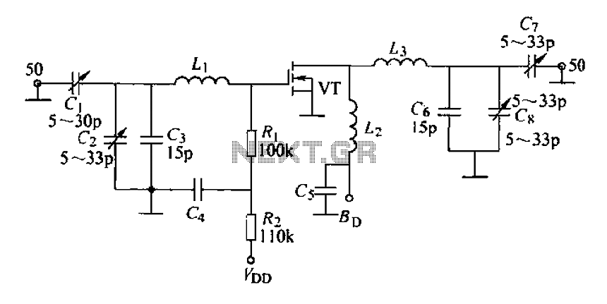
A 175 MHz high-frequency amplifier circuit utilizing a field-effect transistor (FET) is presented. The field-effect transistor used is the 3D04H, along with its associated components and parameters. The 175 MHz high-frequency amplifier circuit is designed to amplify signals in the...
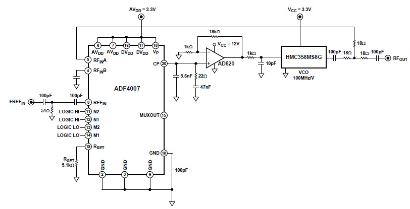
The ADF4007 high-frequency divider Phase-Locked Loop (PLL) synthesizer can be utilized in a variety of communication applications. It operates up to 7.5 GHz on the RF side and 120 MHz at the Phase Frequency Detector (PFD). The device includes...
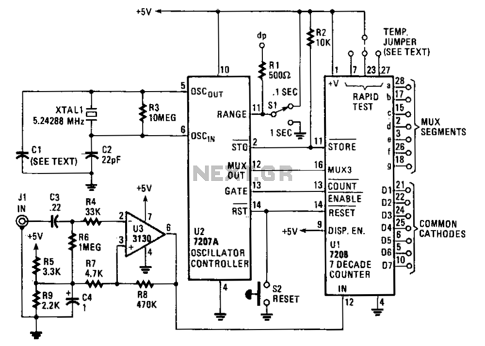
The circuit comprises an ICM7208 seven-decade counter (U1), an ICM7207A oscillator controller (U2), and a CA3130 biFET operational amplifier (U3). The ICM7208 (U1) counts input signals, decodes them into a 7-segment format, and outputs signals to drive a 7-digit...