
Geiger Counter Schematic Help
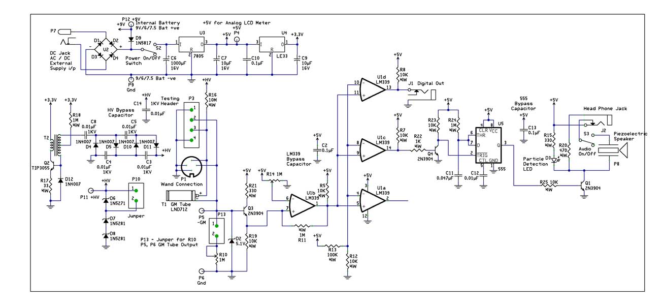
- Lower Left Corner: "D9," a 9V battery, some capacitors, and a 7805 voltage regulator. This section appears to convert 25VDC to 5VDC with adequate current capacity while providing battery backup. The 7805 is similar to its application in the NerdKit. It is believed that the Vcc from this section supplies power to the "Vcc" sections elsewhere in the schematic, although this may not be entirely accurate.
- Left Central: U1a-d, "D1," capacitors, resistors, Q1, T1 (left side). This section functions as a square wave pulse generator to drive the transformer T1. Other diagrams have shown a hex inverter IC (U1 pins a-d) used in conjunction with a resistor-capacitor configuration to produce a square wave output. This section can be likened to a heavy-duty version of a 555 timer that does not utilize a 555 IC.
- Right Upper Central: T1 (right side), D2-6, capacitors. This area generates high power DC. The transformer steps up the square wave DC to a higher voltage, resulting in a distorted square wave. The diodes and capacitors then rectify this to a semi-steady DC voltage. Zener diodes D4-6 regulate the voltage to the GM tube at approximately 500VDC, while resistor R4 limits current to prevent arcing within the GM tube.
- Mid Far Right: Q2, U1e, capacitors, resistors. The GM tube produces a very fast but small pulse (in the nanosecond to microsecond range). The transistor and inverter, along with the capacitor and resistor, shape these pulses to a +5/0V signal suitable for U2, while also preventing high voltage from reaching U2. The transistor functions as a crude amplifier in this section, converting the tiny pulses from the GM tube into more recognizable logic transitions.
- Lower Right Central: U2, capacitors, resistors, speaker, LED, headphone jack. U2 is a 555 timer configured as a pulse stretcher, converting the microsecond pulses from the previous section into a longer pulse that can be visually indicated by an LED or audibly signaled through a speaker. This application is common for 555 timers, and most datasheets provide examples of similar configurations. The roles of the LED, speaker, and headphone jack are considered self-explanatory.
The described circuit represents a functional Geiger Counter design that effectively converts radiation detection into a readable format, utilizing various electronic components to achieve the desired signal processing and output. Each section of the circuit plays a critical role in ensuring accurate detection and representation of radiation levels, making it a valuable tool for monitoring environmental conditions.With the recent events at the Fukushima Dai-ichi nuclear power plant, I thought it would be pretty cool to build a Geiger Counter and hook it up to my NerdKit for interfacing with my computer. I`ve found this article which explains the building process pretty well, and also includes a schematic: Unfortunately, the section that describes the circui
t really doesn`t explain how the circuit works. This may be a huge request, but could somebody do a writeup on this circuit that explains what each component does to get the end result I`ve been looking over the circuit but my inexperience with such schematics isn`t helping at all. I am not an electrical guru, but from what i can read most of the schematic makes sense, althought the power part is really messy.
I have broken out a few of the sections below with what I believe they do. Any of the pros around here should feel free to jump in and point out where i am going wrong. hopefully it helps, but if you want more detail I will try. -Lower Left Corner : "D9", a 9v battery, some caps and a 7805 - This looks like a way to convert the 25VDC to 5VDC with decent current capacity and have a battery backup. The 7805 portion is very similar to how it is used on the NK. I think the Vcc leaving this section is being used to feed the "Vcc" sections elsewhere in the diagram, but I migh be wrong.
- Left Central: U1a-d, "D1", caps, resistors, Q1, T1 left side - This is a square wave pulse generator to feed the transformer T1. I have seen other diagrams where a hex inverter IC (U1 pins a-d) is used with an ResistorCapacitor setup to create a square wave output train.
(think of this section as heavy duty 555, that doesn`t use a 555 per say) - Right Upper Central: T1 right side, D2-6, caps - This section on the right side of T1, is the high power DC generation section. The transformer steps the squarewave DC up to a higher voltage ugly square wave and then the diodes and caps clean it up to a semi-steady DC.
The Zeners, D4-6, effectively "regulate" the voltage to the GM tube at ~500Vdc. R4 is of course to keep the current down and prevent arcing inside the GM tube. -MidFarRight: Q2, U1e, caps, resists - The GM tube outputs a very fast (nano-microsec) but very small pulse. the transistor and inverter with the help of the capacitor and resistor, shape the pulses to +5/0V in the proper orientation for U2 and keep the high voltage from getting to the U2.
The transistor acts like an crude amplifier in this portion, making the tiny blips out of the GM tube closer to logic transistions. -Lower Right Central: U2, caps, resistors, speaker, LED, headphone jack - U2 is a 555 being used as a pulse stretcher to take the ysec pulses from the previous section and convert them into a pulse that is visible when flashed on an LED or Audible when put on the speaker.
This is a very typical use for 555`s and most datasheets have a diagram of them being used like this. I am going to assume the LED, speaker, and headphone jack are pretty self-explanitory. 🔗 External reference
Related Circuits
There are two primary methods to control the speed of a DC motor: by varying the supply voltage and through pulse width modulation (PWM). The first method is less convenient, particularly in digital systems, as it necessitates the use...
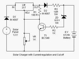
By adjusting the Adjust pin, the output voltage and current can be regulated. A variable resistor (VR) is connected between the Adjust pin and ground to achieve an output voltage of 9 volts to the battery. Resistor R3 limits...
This website was developed to assist students in discovering ideas for their projects or final year projects (FYP). All content presented here is sourced from reliable blogs, websites, and forums. The owner of this website assumes no responsibility for...
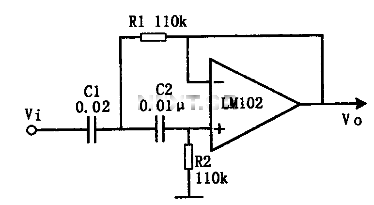
This document presents an active low-pass filter circuit with a cut-off frequency (fc) of 10 kHz. The circuit allows for various values for the ratios of resistors R1 and R2, as well as capacitors C1 and C2. Specifically, it...
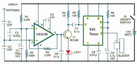
This electronic schematic allows for the design of a simple cellular phone detector circuit capable of sensing the presence of an activated mobile phone from a distance of 1.5 meters. The capacitor C3 should have lead lengths of 18...
This circuit is very simple, consisting of fewer than 12 components, designed to build a DC to AC converter. The principle of this circuit involves generating a 50/60Hz frequency using the IC CD4047. The output from pins 10 and...