
By setting the cutoff frequency of the programmable digital low-pass filter
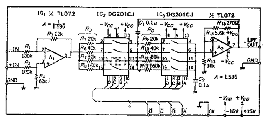
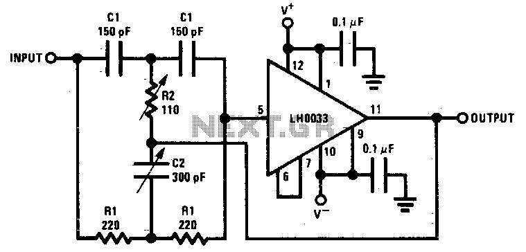
The circuit described is a sophisticated implementation of a dual Butterworth filter configuration, optimized for a feedback amplifier application. The design leverages the Butterworth filter's characteristic of providing a maximally flat frequency response in the passband, making it suitable for applications requiring high fidelity and minimal distortion.
The differential input amplifier design, with one input grounded, ensures that the circuit operates effectively as a single-ended amplifier. This configuration is particularly useful in scenarios where noise rejection is critical, as it allows for the cancellation of common-mode signals.
The feedback resistor, Rs, plays a crucial role in determining the gain of the amplifier. The selection of 63.92 kΩ provides a balance between the desired gain and the stability of the amplifier. The choice of standard resistor values, such as 62 kΩ, simplifies the procurement and assembly process while maintaining performance integrity.
The use of a 0.1 µF capacitor for setting the cutoff frequency is a practical approach, as it allows for easy adjustments to be made in response to varying application requirements. The calculated output impedance values at different frequencies indicate the amplifier's performance characteristics across the intended frequency range. The noted decrease in output impedance with increasing frequency is a typical behavior of passive filter designs, which must be accounted for in system integration.
The design's flexibility in adjusting the cutoff frequency from 0 to 80 Hz enhances its applicability across various audio processing tasks, making it suitable for equalization and other signal processing applications. The implementation of high feedback resistance mitigates the impact of switch resistance, ensuring that the performance remains within acceptable limits, thus enhancing the overall reliability of the circuit.
In summary, this dual Butterworth filter feedback amplifier circuit is a well-engineered solution for high-fidelity applications, combining effective noise rejection, adjustable frequency response, and robust performance characteristics. Proper component selection and configuration are key to achieving the desired operational parameters while ensuring minimal distortion and optimal signal integrity.As can be seen from the circuit loop, the circuit is mainly two times a Butterworth filter, in order to make a 0.707, magnification feedback amplifier d was d 3- (1/Q) 1. 5860 input amplifier a differential input type, but also to one input is grounded, with only one input terminal, and wherein attenuation filter gain should amount (I.58 6-fold) are equal, in order to ensure that the passband gain of OdB. Feedback resistor Rs is 63k92 (Rs I00 kO 1. 568 63kQ), take the closest series resistance is 62 kC20 on the frequency setting resistor set -: mouth i.Ca using readily available 0,1 F capacitor, according to the lowest frequency (ie, the cutoff frequency of each file) calculation chu.
When, 10Hz, the ugly. 1 only stone 0 * 1 l0-ox 10 159. 2kQ}, 20Hz time, Ro 159,2kC) xl/2 79.6k O, 40 Hz, the clamor. 39, 8kQ, increments every two times, said o reduces 1/2 0 if the lowest frequency, whichever is 30Hz, and ugly as the work level, alum was 53. 33kQo by setting L ~ 1 of 5 data, you can make the change in the cut-off frequency fc] O ~ isOHz range.
Due to a series of on-resistance analog switch, in order to minimize errors, R. With a high resistance, minimum resistance to 20kQ, assuming that r. - 500, cut-off frequency lower than the calculated value of 0.25%, the election is practically permissible. The circuit of each file by frequency IOHz, if each file up-iOOH ztCL.g Wang capacity should be changed to 0.
OILiFo
Related Circuits
A wide range frequency meter is a useful tool for an electronics lab. This project describes a frequency meter based on the AT90S231 microcontroller that can measure input frequencies up to 50 MHz. The measured frequency is displayed on...
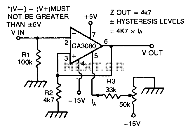
The CA 3088 is utilized as a versatile Schmitt trigger. The magnitude of the hysteresis levels is determined by the current (Ia) flowing out of the amplifier's output and through resistor R2. An increase in Ia results in an...
This digital volume control has no pot to wear out and introduces almost no noise in the circuit. Instead, the volume is controlled by pressing UP and DOWN buttons. This simple circuit would be a great touch to any...
Component value sensitivity is extremely critical, as are temperature coefficients and matching of the components. Best performance is attained when perfectly matched components are used and when the gain of the amplifier is unity. To illustrate, the quality factor...

The two circuits illustrate the generation of low-frequency sine waves by shifting the phase of the signal through an RC network, enabling oscillation when the total phase shift reaches 360 degrees. The transistor circuit on the right produces a...
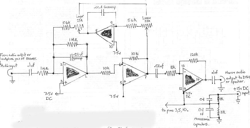
The audio bandpass filter described is beneficial for amplifying and filtering weak AM TV video carriers. For instance, a digital frequency audio multimeter (DFM) may lack sufficient input sensitivity for measuring extremely weak single sideband (SSB) TV video audio...