
+5V Supply Circuit
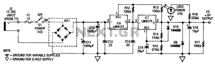
The power supply circuit is designed to convert the AC voltage from a standard wall transformer into a usable DC voltage suitable for various electronic applications. The wall transformer (T2) steps down the mains voltage to 12 volts AC, which is then rectified and filtered to produce a stable DC output.
The circuit typically includes a rectifier, often a bridge rectifier configuration, which consists of four diodes arranged in a bridge format to efficiently convert the AC voltage to pulsating DC. Following the rectifier, a smoothing capacitor is employed to filter out the ripples in the output voltage, providing a more stable DC level. The value of this capacitor is chosen based on the load current and the acceptable ripple voltage.
In addition to the basic components, a voltage regulator may be included to ensure that the output voltage remains constant despite variations in load current. This feature is particularly important in laboratory settings where precise voltage levels are required for testing purposes.
Moreover, the circuit may incorporate additional features such as fuses for overcurrent protection, indicator LEDs for power status, and adjustable resistors or potentiometers to allow for fine-tuning of the output voltage.
Overall, this power supply circuit is a fundamental component in electronic laboratories, providing a reliable source of power for testing and development of various electronic circuits. The power supply shown is designed to operate from a wall transformer. This circuit can be used in conjunction with a variable supply to test circuits in the lab, etc. T2 is a 12-V wall transformer. 🔗 External reference
Related Circuits
Nissan Sentra 1.6 Liter Manual Transmission Starter Circuit Wiring Diagram. The Nissan Sentra 1.6 Liter manual transmission starter circuit wiring diagram provides a visual representation of the electrical connections involved in the starting system of the vehicle. This diagram is...
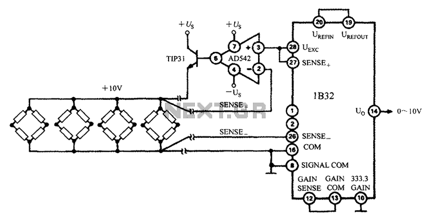
The 1B32 application circuit features multiple pressure sensors as illustrated in the figure. Excitation power is supplied through the AD542, which is followed by a TIP32 transistor that drives multiple bridge sensors. The AD542 operates as a Bi-FET in...
Operational amplifiers (op-amps) are highly versatile components in electronic circuits. However, one significant limitation is their need for a dual power supply, which can restrict their use in applications where a dual supply is impractical or cost-prohibitive. The circuit...
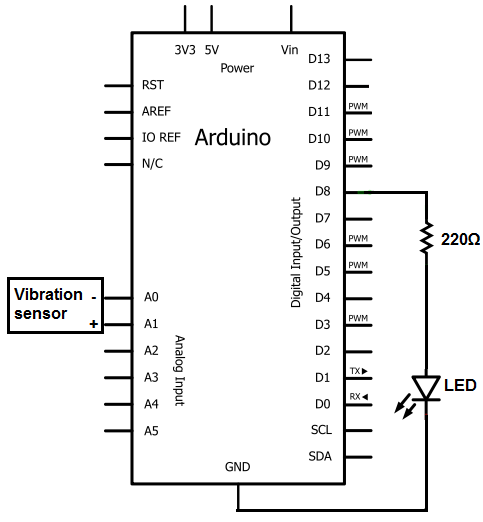
The sensors consist of a thin strip of piezoelectric material with a rivet at one end acting as a weight. When vibration occurs, the weight moves, stressing the piezo material, which generates a spike in voltage that can reach...
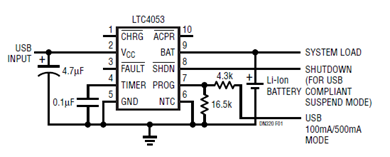
The schematic presented illustrates a minimal component solution for a USB battery charger utilizing the LTC4053 integrated circuit (IC) to create a fully compliant USB charger. This IC functions as a standalone linear charger designed for lithium-ion (Li-ion) batteries,...
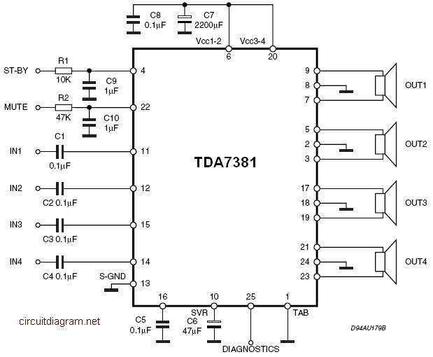
The TDA7381 is a Class AB audio power amplifier housed in a Flexiwatt25 package, specifically intended for car radio applications. This circuit can also be utilized for various other purposes. The fully complementary PNP/NPN output configuration enables a rail-to-rail...