
Low impedance pre amp circuit diagram
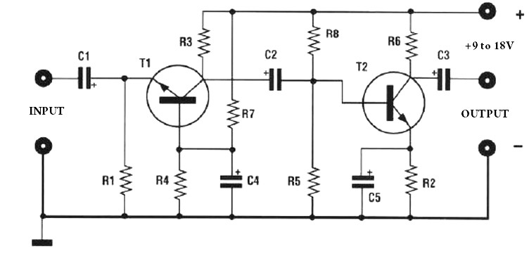
The preamplifier circuit is designed to achieve high gain, making it suitable for applications requiring signal amplification from low-level sources. The use of a trimmer resistor (R3) allows for fine-tuning of the gain, providing flexibility in adjusting the amplification to meet specific requirements. The series configuration of R3 ensures that the gain can be decreased as needed, which is particularly useful in preventing saturation or distortion of the amplified signal.
Powering the circuit with a voltage supply between 9 and 18 volts offers versatility, allowing it to be integrated into various systems where different power supply voltages are available. This range provides sufficient headroom for the operational amplifier or transistor used in the preamplifier, ensuring optimal performance across different operating conditions.
The circuit layout should be followed closely to ensure proper functionality. It is essential to pay attention to the orientation of components, particularly polarized capacitors and diodes, as incorrect placement can lead to circuit failure. The layout should also consider minimizing noise and interference, which can be achieved through careful routing of signal and power traces, as well as grounding practices.
In summary, this preamplifier circuit is designed for high gain with adjustable output through a trimmer resistor and is capable of operating within a specified voltage range, making it a versatile choice for various electronic applications.The amplification of this pre amp is therefore very high, whether to reduce, there should be a trimmer R3 series to 100 ohms. The system can be powered by a voltage of between 9 and 18Volts. for its realization, follow the diagram layout. 🔗 External reference
Related Circuits
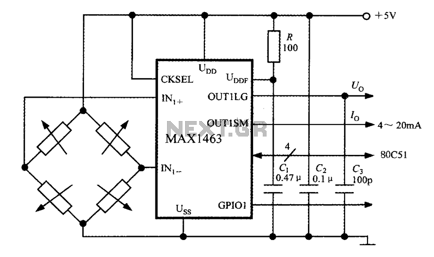
The system consists of a MAX1463 precision pressure detection circuit block diagram. The output voltage from the bridge pressure sensor is connected to the MAX1463 inputs IN1+ and IN1-. Controlled by a CPU, the pressure signal undergoes nonlinear calibration...
The motor protection circuit consists of a power supply circuit, a current detection circuit, and a protection control circuit, as depicted in the accompanying diagram. The power circuit includes a power transformer (T), a rectifier diode (VD4), filter capacitors...
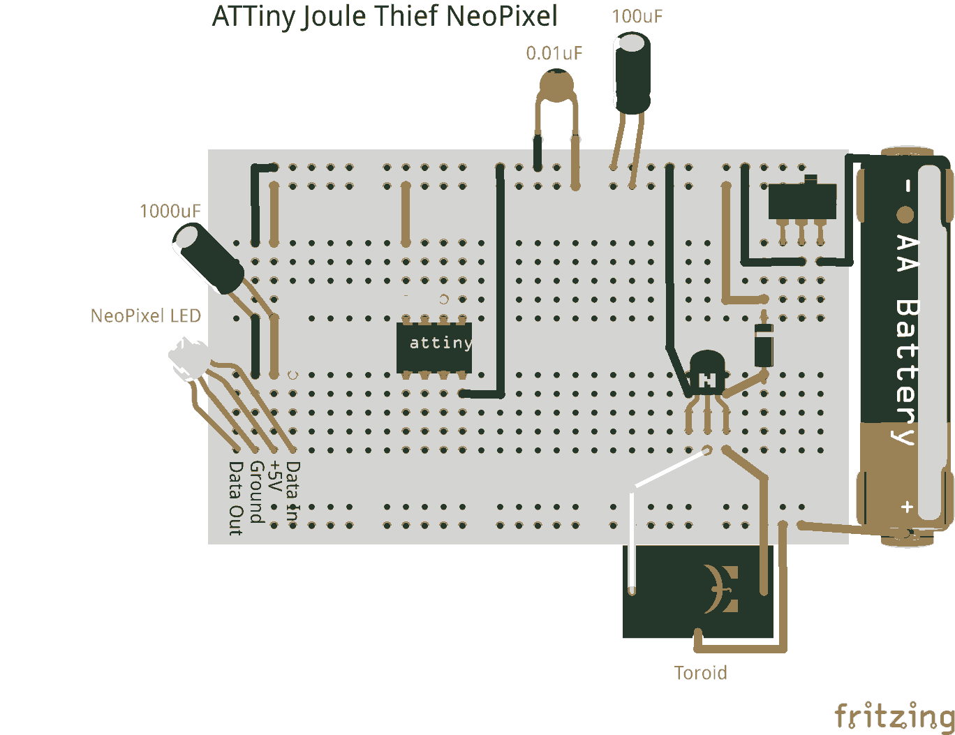
Joule thieves are not limited to illuminating standard LEDs. They can be utilized with an ATtiny microcontroller to power NeoPixel LEDs. Joule thieves are simple and efficient circuits designed to extract and boost low voltage energy from sources such as...
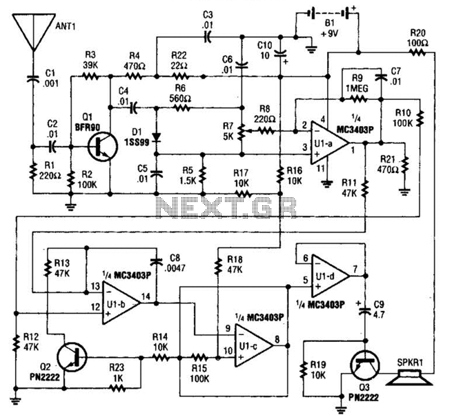
The circuit is constructed around a single integrated circuit (U1), specifically an MC3403P quad op-amp, three transistors (Q1-Q3), and several supporting components. It receives its input from the antenna (ANT1). The signal is processed through a high-pass filter composed...
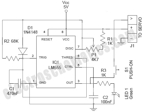
A servo is an error-sensing feedback control mechanism used to correct the performance of a system. A servo motor is a DC motor equipped with a servo mechanism. A servo motor is an electromechanical device that utilizes a closed-loop control...
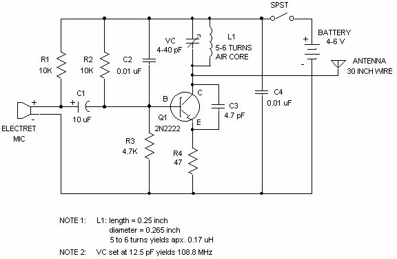
Wireless FM Transmitter. The site provides some explanation on how the circuit operates; however, there are uncertainties regarding certain components, including the electret microphone and the frequency modulation process. The electret microphone operates at a current of 200 µA,...