
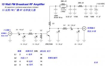
15W FM RF Amplifier with 2SC2539
The FM transmitter circuit is designed to operate efficiently within the FM band, utilizing the BF494 transistor for audio modulation. The circuit's architecture allows for a straightforward assembly process, making it accessible for hobbyists and professionals alike. The MFE201 transistor serves as the core component for the common-emitter configuration, which is essential for achieving the desired amplification and signal clarity.
In addition to the FM transmitter, the shortwave transmitter based on the BEL1895 IC expands the project’s versatility, enabling communication over a broader frequency range. The incorporation of a microphone amplifier allows for direct audio input, which is crucial for applications in educational settings or experimental setups. The variable frequency oscillator provides flexibility in tuning, ensuring that the transmitter can adapt to different operational environments.
The RF amplifier circuit is a critical component in enhancing signal strength, making it ideal for applications that require robust signal transmission. The design utilizes the 2SC1970 transistor, known for its reliability in RF applications, ensuring that the circuit can handle the necessary power levels while maintaining performance. This circuit can be further optimized by experimenting with different transistor types, allowing for customization based on specific requirements or constraints.
Overall, this collection of circuits offers a comprehensive solution for various RF and audio transmission needs, demonstrating the potential for both educational and practical applications in electronics.This the Good Quality FM transmitter for your stereo or any other amplifier gives you a pretty good signal strength up to a range of 500 metres having a power output of about 200 mW. This circuit can be operated with a 9V battery. The audio-frequency modulation stage is constructed close to transistor BF494 (T1), . By working with only a small han dfull of parts you can assembled this kind of reliable FM Amplifier. It runs with only 1 UHF/VHF type transistor, MFE201. This amplifier will pull in all distant FM stations clearly. The circuit is configured as a common-emitter tuned RF pre-amplifier wired around VHF/UHF transistor MFE201. You will find. Here the SW transmitter circuit based on IC BEL1895. This particular transmitter circuit works in shortwave HF band (6 MHz to 15 MHz), and can be applied for shortrange communication and for educational purposes.
The circuit is composed of a mic amplifier circuit, a variable frequency oscillator, and modulation amplifier stages. Transistor T1 (BF195) is. Easy FM tracking transmitter project :). The circuit designed by Tony van Roon, and here the FM tracking transmitter diagram: Components List: R1 = 10K C1 = 100uF/10V C2 = 10nF C3 = 4-40pF trimmer capacitor C4 = 4.
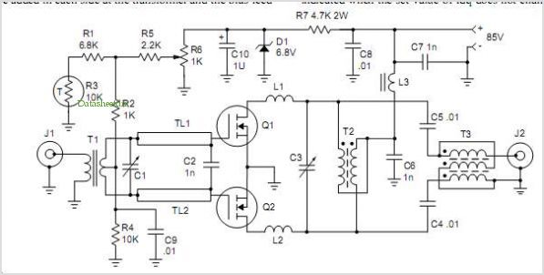
7pF IC1 = LM3909 Q1 = 2N3904 NPN transistor LED1 = Red LED/or another color as you. This diagram is a schematic diagram of RF amplifier circuit. The circuit will amplify the RF signal about 10 times, 100mW input power to 1. 3W output power. It use a general NPN RF transistor 2SC1970. You may apply other transistors, for example 2N442. Circuit Diagram: Circuit Works: RF system and specially in RF amplifiers, this. 🔗 External reference
Related Circuits
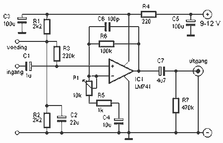
This preamplifier uses a type of IC 741 and can boost a microphone signal to line level. The microphone signal is connected to the input port. Any power for the microphone jack of the food are met. Here half...
The converter depicted in Figure 1 utilizes a component from the PeakSwitch family (U1, a PKS606YN) to operate a 36 W motor, capable of handling startup and load transition peaks of up to 72 W. The motor speed can...
Although many album titles that were once available on vinyl are gradually being released on CDs, not all titles are accessible. It is possible that there are valuable records in a collection that one might wish to convert to...
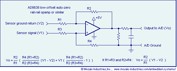
Ground loop offset errors and ground noise are eliminated by a differential amplifier or instrumentation amplifier before the analog-to-digital (A/D) conversion. The differential input amplifier addresses ground loop errors, allowing for precise measurement of non-isolated sensors. A simple operational...
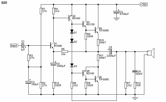
Figure 1 shows the circuit. A major change from all of the designs from that era is the speaker coupling capacitor - 1000uF (for a -3dB of 20Hz and a 8 Ohm load) was the most common value. This is...
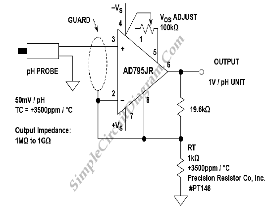
A buffer amplifier is necessary for a typical pH probe to isolate its source resistance, which ranges from 10^6 to 10^9 ohms, from the external circuitry. Such an amplifier is illustrated in the... The buffer amplifier serves a critical role...
Warning: include(partials/cookie-banner.php): Failed to open stream: Permission denied in /var/www/html/nextgr/view-circuit.php on line 713
Warning: include(): Failed opening 'partials/cookie-banner.php' for inclusion (include_path='.:/usr/share/php') in /var/www/html/nextgr/view-circuit.php on line 713