
16 bit sound
The circuit design for the DIY 16-bit sound upgrade for the Risc PC can be outlined as follows:
1. **Digital Output Connection**: The digital output from the VIDC chip is connected to the header LK8, where it transmits the I²S format audio signals. This connection is crucial for ensuring that the digital audio data is accurately fed into the DAC.
2. **DAC Selection**: The TDA1543 DAC is chosen for its compatibility with I²S signals and favorable pricing. The DAC is connected to the appropriate pins on LK8 to receive the digital audio data.
3. **Clock Generation**: An 11.2896 MHz crystal oscillator is integrated into the circuit to provide the necessary clock signal for the VIDC and DAC. The output of the oscillator is connected to the clock input of the VIDC to ensure proper timing for digital audio processing.
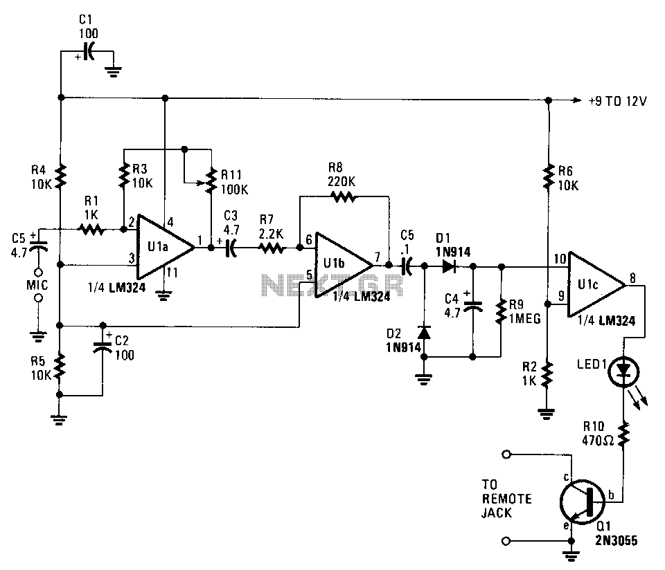
4. **Analog Output Filtering**: The analog output from the DAC is then routed through a low-pass filter, implemented using half of an LM324 operational amplifier. This filter removes high-frequency noise and ensures a clean audio signal.
5. **Audio Mixing**: The filtered audio signals are fed into a mixer circuit, utilizing the other half of the LM324. This mixer can combine the new 16-bit audio output with the existing 8-bit sound output from LK14, allowing for seamless audio integration.
6. **Final Output**: The mixed audio output can be connected to standard audio equipment, enabling playback through speakers or headphones.
This circuit effectively upgrades the Risc PC's audio capabilities, providing enhanced sound quality while maintaining compatibility with existing systems.On several occasions, Acorn`s initial specifications for a new machine and the final product have differed considerably in the features they provide. For example, the Risc PC`s motherboard SCSI controller and Phoebe`s ultra-fast scratch memory were consigned to history before ever seeing the light of day.
These were mainly as a result of cost-cutting measures on Acorn`s part when the production cost of the final system was totted up. Another such casualty was the 16 bit sound system in the Risc PC, which was dropped on initial release to save a few pounds of parts. Acorn later realised that in the quantities they were dealing with, the cost of parts was tiny, so reintroduced this feature to motherboards that were shipped with RISC OS 3.
6 or 3. 7, but this left thousands of machines out there with the old system. Since the systems are different to access, software started to appear (such as PC Pro) that would not produce sound on the earlier machines. As the software to drive 16 bit sound is included in RISC OS 3. 6 or later, all that is required is the sound hardware. As the cost of parts is apparently so small, would it be possible to build a DIY 16 bit sound upgrade Commercial cards are available, so it must be possible, so I set out to find out.
The 16 bit sound system in a Risc PC gives a sound output in digital format, which has to be fed to a DAC (Digital to Analogue Converter) to produce audio. Acorn`s costcutting measures meant this DAC and its associated clock were not present on early motherboards, so this is what we have to provide.
The digital sound output arrives on the header LK8 directly from the VIDC chip in I ²S format. This is a standard devised by Philips for interconnecting digital audio components in CD players, DAT drives and so on. It is a serial output, where the 32 bits of each stereo sample (16 left, 16 right) are clocked out in succession: As this is a standard, there are a number of DAC chips that exist that take these signals and produce audio, from Philips Semiconductors among others.
While they would all do the job, they tend to be somewhat specialist and so only available from suppliers who have a minimum order of 1000 and a lead time of 12 weeks while they ship them from the factory. I found Cricklewood Electronics had the TDA1543 for around £2. 50 and let you order on sensible terms, so that is what I used. Now, we need to provide a clock to give the VIDC and DAC the correct timing. The Risc PC technical reference manual and VIDC20 datasheet are somewhat vague about this, but after a little experimentation I found that an 11.
2896MHz clock (which is a multiple of the 44. 1KHz sample rate that RISC OS uses) worked when fed directly to the VIDC, and RISC OS 3. 6 or higher handles setting up the VIDC registers to use this. Finding a source of 11. 2896MHz crystal oscillators to provide this frequency accurately was a much bigger problem than finding the DAC, but in the end C-MAC kindly offered me a free sample, which solved this problem. A faster/slower crystal will work, but this causes a corresponding change in the pitch of the sound output which may cause speech to sound strange.
Here, the oscillator provides the clock to the VIDC on LK8 to generate its serial outputs. These arrive on the other pins of LK8 and are fed to the DAC. This produces two channels (left and right) of audio, which then get filtered by half of the LM324 to remove unwanted inaudible high frequencies generated as a result of the digital to analogue conversion process. At this point the signals are standard audio, so stages after this could be replaced by any audio system to suit your needs.
In this circuit, the filtered outputs then pass to a mixer comprising the other half of the LM324, which can mix them with any number of audio sources. In this case, they are mixed with the existing 8 bit sound output provided on LK14, although for a few extra components t
🔗 External reference
Related Circuits
This circuit can cause a cassette recorder to automatically turn on and record when a sound or noise is present. Another use is when the sound-activated switch is used to turn on a cassette player, allowing it to function...
The TDA3567 is a monolithic integrated decoder designed for the NTSC color television standards. It incorporates all the necessary functions for the demodulation of NTSC signals. Additionally, it features a luminance amplifier and an RGB matrix amplifier. These amplifiers...
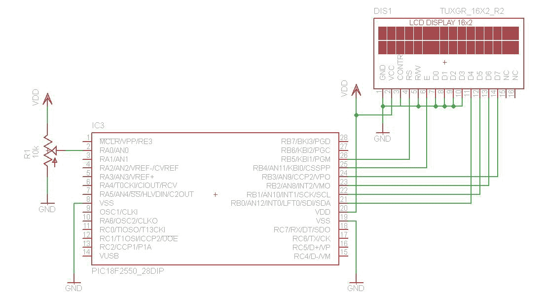
The analog to digital converter (ADC) is commonly required in most of the projects. Analog voltage measurement can be done using the ADC hardware built in together in a PIC. The picture below shows a simple setup for measuring...
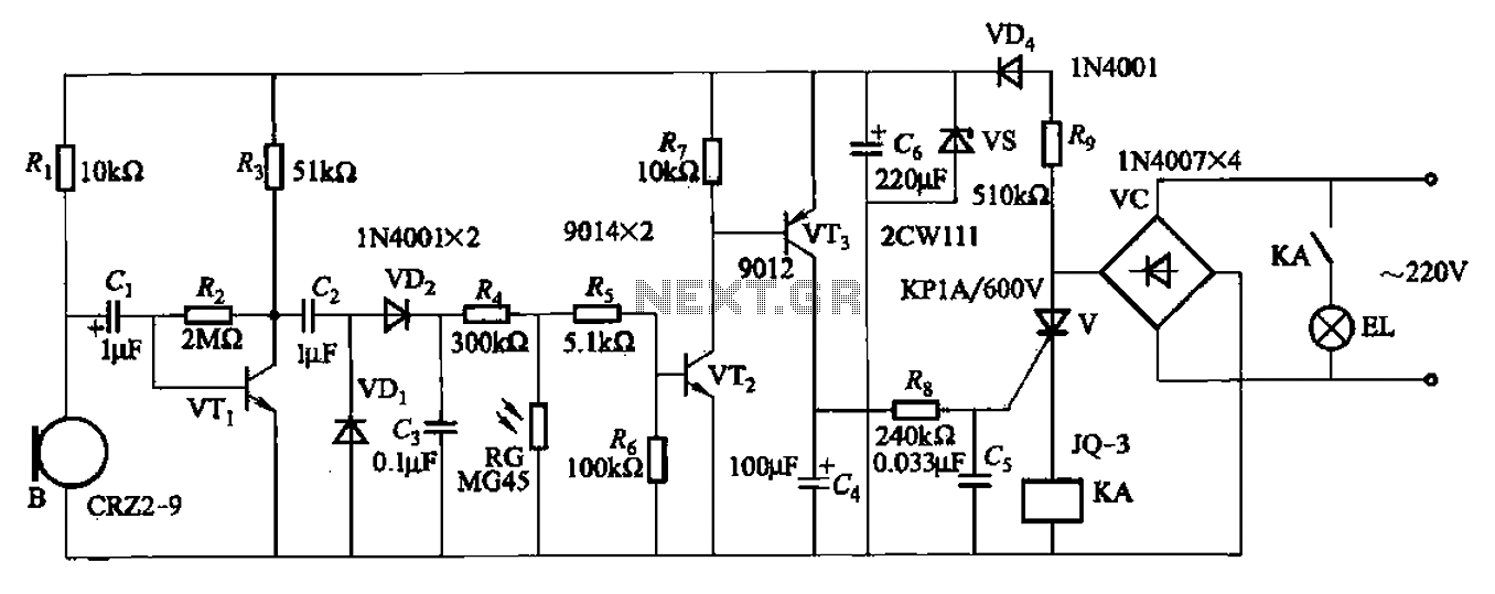
A resistor R8, capacitors Cd, and a thyristor V AC switch form a delay circuit. The lamp's lighting delay time is determined by the resistor Rs and capacitor C4, with a delay of approximately 40 seconds as indicated in...
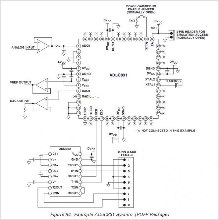
The ADUC832 MicroConverter is a fully integrated 12-bit data acquisition system-on-a-chip. Like all of Analog Devices' MicroConverter products, it features precision A/D and D/A conversion along with a Flash Microcontroller on a single chip. The ADUC832 is completely hardware...
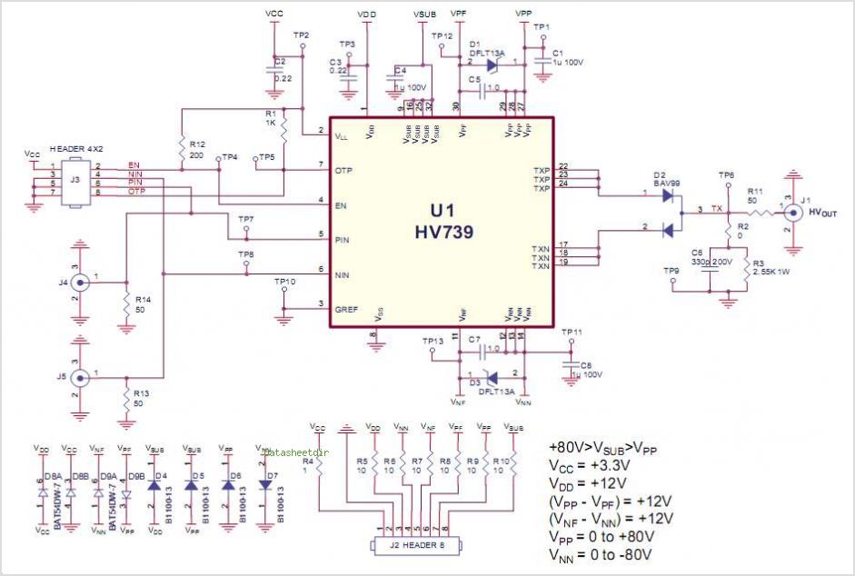
This demo board data sheet explains how to utilize the HV758DB1 to produce a fundamental high voltage pulse waveform for use as an ultrasound transmitting pulser. The HV758 circuit employs a DC coupling method in all level translators, eliminating...