
160 METER VFO
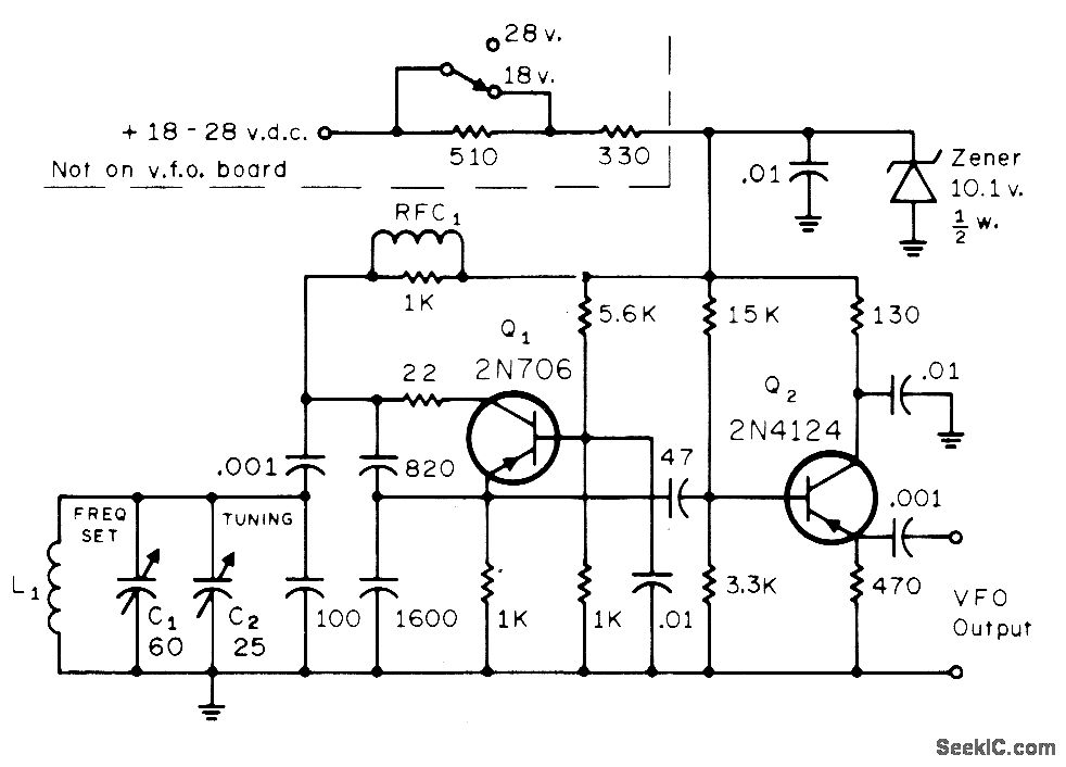
The Colpitts oscillator configuration is characterized by its use of a combination of capacitors and an inductor to establish the resonant frequency, which is determined by the values of these components. In this circuit, Q1 serves as the active component, providing gain and oscillation, while Q2 functions as an emitter-follower, buffering the output and ensuring that the load does not affect the oscillator's performance. The use of Zener diodes for voltage regulation is critical in maintaining a consistent output voltage, which is especially important in battery-operated devices where voltage levels may fluctuate.
The output voltage of approximately 0.7 VRMS indicates that the oscillator is designed to deliver a modest signal level, suitable for driving subsequent stages without distortion. The potential for parasitic oscillation is a common concern in oscillator designs, particularly in high-frequency applications. The tuned stages that follow the VFO are essential for filtering out these unwanted oscillations, ensuring that only the desired frequency is amplified and transmitted.
The choice of L1, with its specific winding parameters, plays a significant role in defining the oscillator's performance. The use of No. 28 enamel wire on an Amidon T-50-2 toroid ensures efficient magnetic coupling and minimizes losses, which is crucial for achieving the desired frequency stability and output power. RFC1, with its inductance value of 850 μH, acts as a choke to block high-frequency noise while allowing the desired signal to pass through, further enhancing the overall performance of the circuit.
In summary, this Colpitts oscillator design demonstrates a well-thought-out approach to achieving stable oscillation and reliable performance in a moderate power solid-state transmitter application, as detailed in the referenced literature. The integration of Zener regulation and careful component selection contributes to the robustness of the circuit, making it suitable for various RF applications.Standard Colpitts oscillator Q1 with emitter-follower Q2 gives dependability and adequate isolation from later stages Zener regulation provides stability even with weak battery Output is about 0. 7 VRMS. Low-level parasitic oscillation may occur about 150 kHz below operating frequency but is suppressed by tuned stages following VFO.
L1 is 52 turns No. 28 enamel on Amidon T-50-2 toroid. RFC1 is 850 H. -A Weiss, Design Notes on a Moderate Power Solid State Transmitter for 1. 8 MHz, CQ, Nov. 1972, p 18-22, 24, 98, 100, and 102. 🔗 External reference
Related Circuits
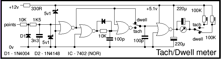
This circuit as first published in Wireless World September 1975 and subsequently in MECRM. It's built around a TTL quad NOR gate, though CMOS could be used. The circuit in question utilizes a TTL (Transistor-Transistor Logic) quad NOR gate, which...
A 7 MHz oscillator with a variable crystal oscillator (VXO) operates very stably, but it allows only a small frequency variation (approx. 5 kHz). In contrast, a VFO with an LC resonant circuit can be tuned over a range...
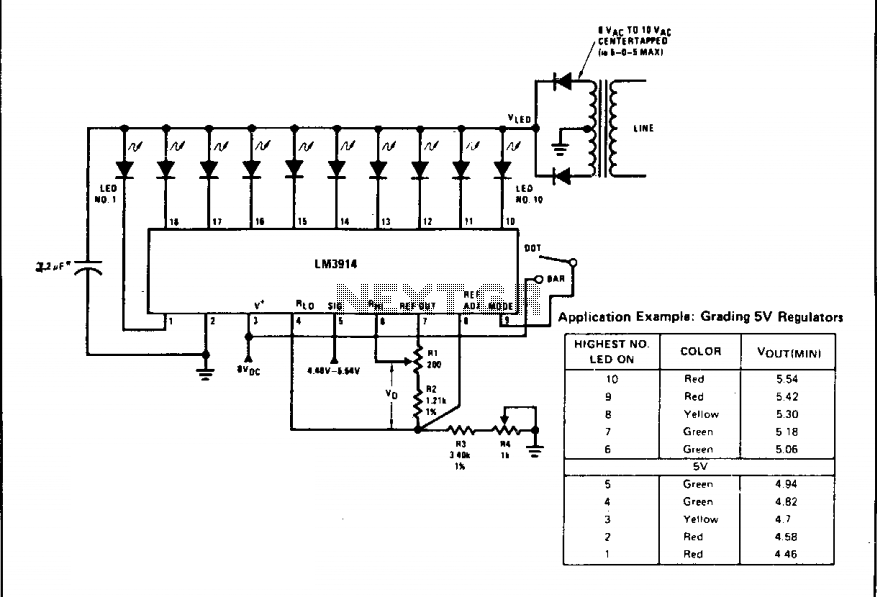
A bar graph driver IC LM314 drives an XED display. The LEDs may be separate or in a combined (integral) bar graph display. Calibration: With a precision meter between pins 4 and 6, adjust R1 for voltage Vq of...
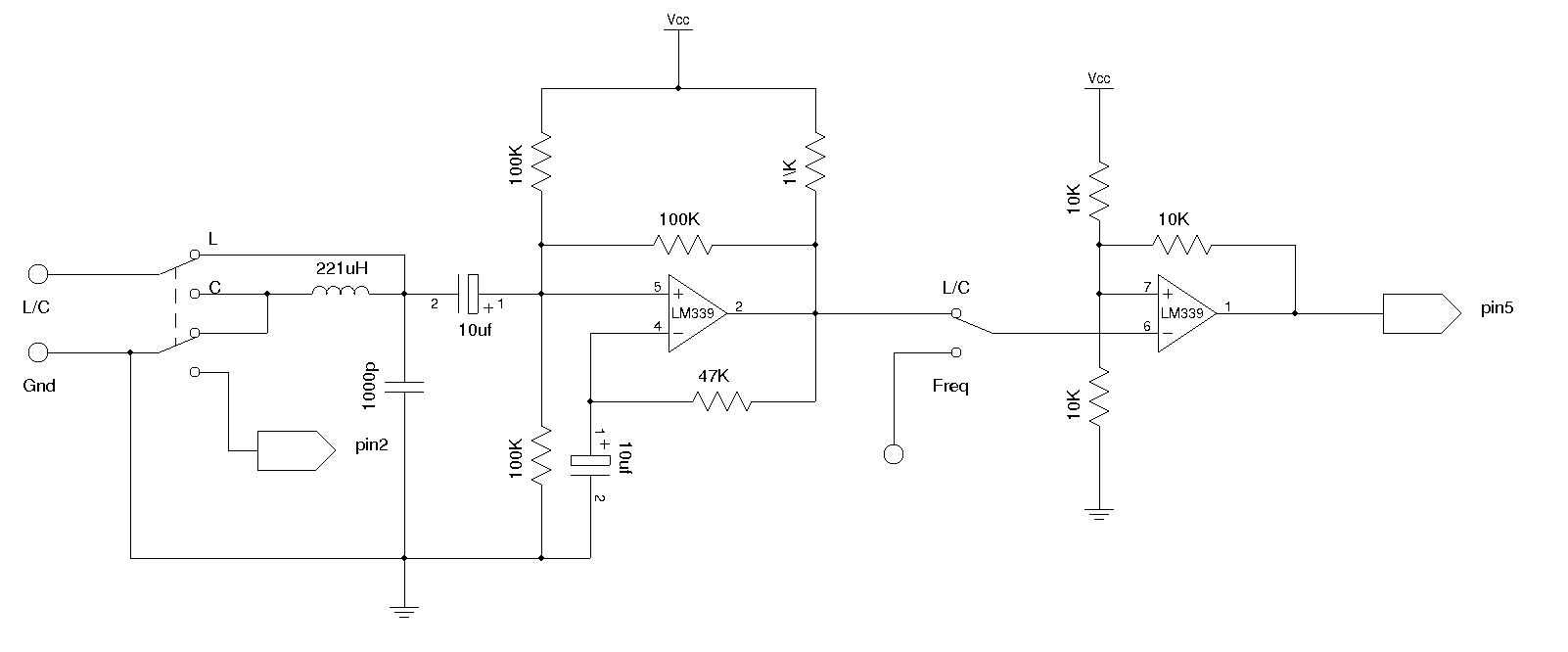
An LC meter is being constructed due to the absence of a multimeter capable of measuring inductance. Although the available multimeters can measure capacitance, they lack accuracy for small capacitance values in the range of several picofarads (pF). While...
Supply voltage: 12 V. Supply current: 10 mA in stand-by, max. 80 mA. Input voltage: min. 20 mV rms. Indication range: 30 dB. LED currents: 7 mA. Ref. voltage of IC2: 5 V More: R1 - trimmer 100 k...
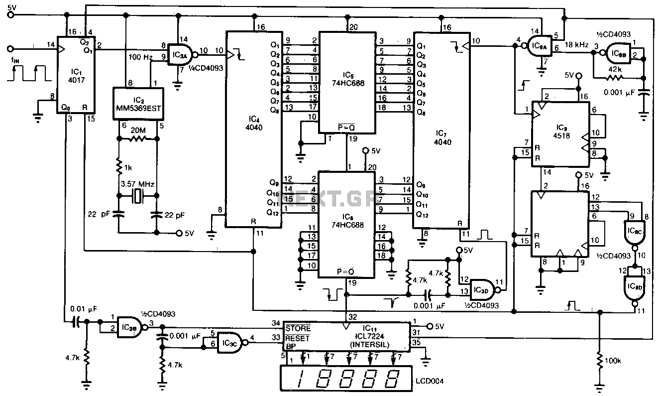
This tachometer allows for the measurement of heartbeats, respiratory rates, and other low-frequency events that occur at intervals ranging from 0.33 to 40.96 seconds. The circuit detects the frequency, calculates the corresponding pulses per minute, and updates the LCD...