
Expanded scale meter

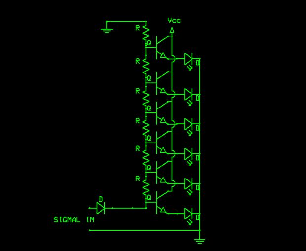
The LM314 is a versatile integrated circuit designed to drive bar graph displays, commonly used in various electronic applications to visually represent data levels. The device can operate with separate LEDs or a combined bar graph display configuration, providing flexibility in design.
In the calibration process, a precision meter is utilized to measure the voltage between pins 4 and 6 of the LM314. The resistor R1 is adjusted to achieve a target voltage (Vq) of 1.20V, ensuring that the output levels are accurate for the intended application. This step is critical for achieving the desired performance of the display, as it sets the reference point for the LED activation thresholds.
Following the adjustment of R1, a voltage of 4.94V is applied to pin 5 of the LM314. This pin typically serves as a reference or control input, influencing the behavior of the driver IC. The next step involves adjusting resistor R4, which controls the current through the LEDs. The goal is to calibrate the circuit so that LED No. 5 lights up just at the correct threshold, indicating that the system is properly calibrated for the specific application.
The non-interacting nature of the adjustments means that changing the setting of one resistor does not significantly affect the other, simplifying the calibration process. This characteristic is particularly advantageous in applications where multiple parameters must be fine-tuned without causing cascading effects on the overall performance of the display.
Overall, the LM314 bar graph driver IC provides an efficient solution for driving LED displays, with straightforward calibration procedures that ensure accurate visual representation of varying signal levels.A bar graph driver IC LM314 drives anXED display. The LEDs may be separate or in a combined (integral) bar graph display. Calibration: With a precision meter be-tvveen pins 4 and 6 adjust Rl for voltage Vq of 1 20V. Apply 4.94V to pin 5, and adjust R4 until LED No. 5 iust lights. The adjustments are non-interacting. 🔗 External reference
Related Circuits
The schematic indicates that the input is routed through a voltage divider. This configuration is essential for the operation of the Schmitt triggers, which all activate under certain conditions. The voltage divider in the schematic serves to scale down the...
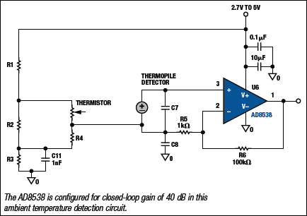
Due to their speed, accuracy, effectiveness, and cost-efficiency, infrared (IR) digital thermometers have supplanted traditional mercury thermometers. An ear digital thermometer utilizes a thermopile sensor to measure the infrared heat emitted by the eardrum, which correlates with the temperature...

This circuit utilizes the CA3100 BiMOS operational amplifier to drive a 1-mA meter movement to its full scale with a 1-V RMS input. The circuit configuration incorporates the CA3100 BiMOS operational amplifier, which is known for its high input impedance...
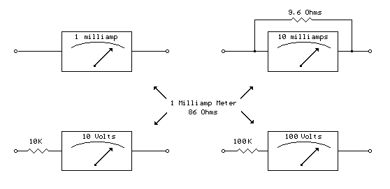
A milliamp meter can be utilized as a voltmeter by incorporating a series resistance. The required resistance is calculated by dividing the full-scale voltage reading by the full-scale current of the meter movement. For example, using a 1 milliamp...
Unlike most surface-mounted device (SMD) resistors, SMD ceramic capacitors do not have their values marked. To determine the value of these capacitors, a capacitance meter is required. SMD ceramic capacitors are widely used in modern electronic circuits due to their...

C1, C2, and C3 are miniature ceramic or plastic trimmers. T1 (main winding) has an inductance of 0.34 µH, utilizing 11 turns of No. 24 enameled wire wound on a T37-10 toroid core. The antenna winding consists of one...