
AVR LC Meter With Frequency Measurement
The construction of an LC meter using the ATmega328P involves several key components and configurations. The heart of the circuit is the LC oscillator, which generates a frequency that varies based on the inductance or capacitance being measured. The oscillator is typically formed by a feedback loop that includes a resistor, capacitor, and inductor. The LM339 comparator, which is a quad comparator, is employed to create the oscillator. Its ability to operate at frequencies up to 50 kHz makes it suitable for the measurement range.
In the LC mode, the oscillator's output is fed into a Schmitt trigger, which provides a clean square wave signal for better frequency measurement. This configuration helps to eliminate noise and ensures that the frequency measurement is accurate. The use of a reed relay allows for seamless switching between measuring inductance and capacitance, enhancing the versatility of the device.
The output frequency is measured using a microcontroller, which can be programmed to calculate the corresponding inductance or capacitance based on the frequency detected. The microcontroller can also be interfaced with an LCD display to present the measurements in a user-friendly format. By utilizing Arduino libraries, the programming becomes more accessible, allowing for quick adjustments and enhancements to the functionality of the LC meter.
Overall, this design provides a cost-effective solution for measuring inductance and capacitance, particularly useful for hobbyists and professionals who require precise measurements in the lower ranges. The flexibility of the ATmega328P, combined with the simplicity of the circuit design, makes it an ideal choice for building a reliable LC meter.Building an LC meter for a while since I do not have a multimeter that is capable of measuring inductance and while the multimeters I have can measure capacitance, they are not able to give accurate readings for small capacitance in the range of several pF`s. There are quite a few good articles on how to build LC metersusing PIC MCUs (like the ones here: 1, 2, 3 ), but instructions on how to build one with an ATmega
MCU are few and far in between, although the basic principle is largely the same. So I decided to write this article on how to build an LC meter using an ATmega328p chip and Arduino libraries. A typical LC meter is nothing but a wide range LC oscillator. When measuring an inductor or capacitor, the added inductance or capacitance changes the oscillator`s output frequency.
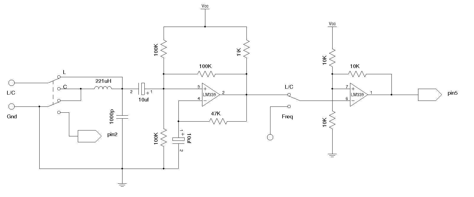
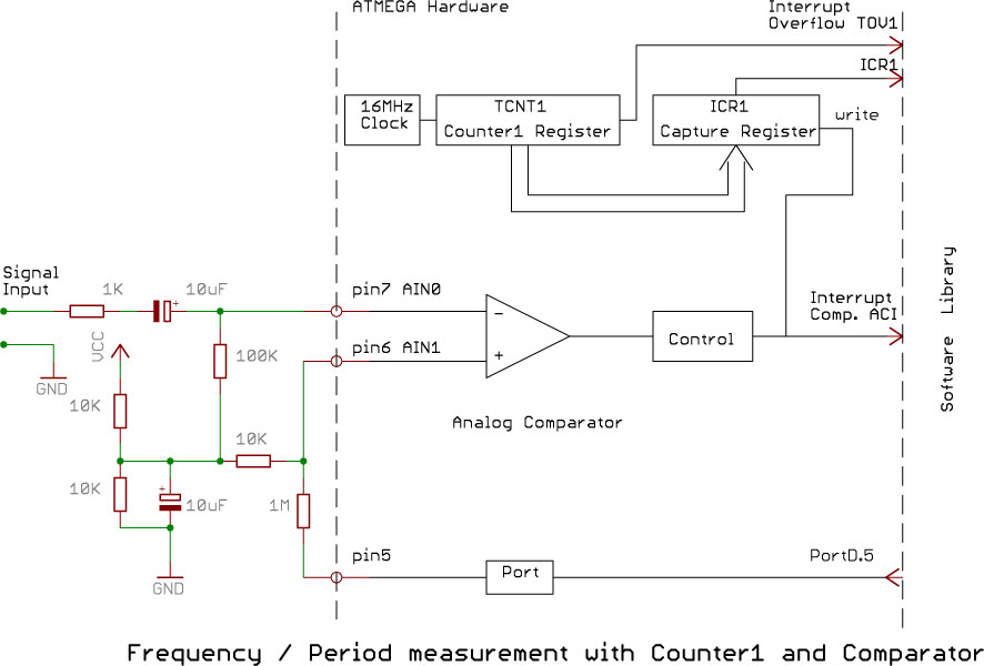
And by calculating this frequency change, we can deduce the inductance or capacitance depending on the measurement. The following schematic shows the comparator based LC oscillator I used in the LC meter. The oscillator portion is quite standard. Most of the other designs I have seen use LM311 comparator. But for this type of application, any comparator capable of oscillating up to 50kHz should be more than sufficient.
I happen to have some spare LM339 ²s lying around so I used it in the oscillator circuit. Because what we are really meausring is the frequency of the oscillator, we can build a frequency meter using the same circuit at almost no additional cost. As you can see in the circuit above, a reed relay is used to switch the measurement from LC mode to frequency mode.
In the schematics above, the second comparator forms a Schmitt trigger to condition the input waveform so that the frequency measurement can be made more accurate. When in the LC mode, the frequency output from the first comparator is simply feed through the Schmitt trigger.
The output frequency is determined by 🔗 External reference
Related Circuits
The circuit was designed to create a high-impedance voltmeter capable of measuring Direct Current (DC) voltages across various types of circuits. The high-impedance voltmeter circuit typically employs operational amplifiers (op-amps) configured in a non-inverting arrangement to ensure minimal loading on...
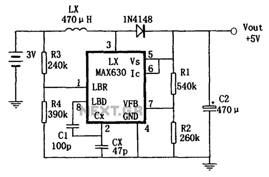
A low voltage frequency circuit utilizes the MAX630 for low battery voltage detection, functioning as an offset boost converter power supply. It is designed to maintain high efficiency (85%) while providing a DC output voltage of 5V at a...
The artwork style of the operational amplifier and the meter face suggests that it is an ACC design from an old issue of ACC Notes. The second image was scanned, and the text below was written from scratch. If...
Software on a MacBook Pro includes Laidman & Katsura's WaveWindow, which functions as a software oscilloscope. It is beneficial for individuals working with sound on the Mac, offering an educational and entertaining experience. Additionally, Faberacoustical's Signal Scope allows for...
VU (Volume Unit) meters used to be the mainstay of audio metering systems, but they have been replaced by LED metering in a great many mixers and other applications. Even in software, the most common level meter is made...
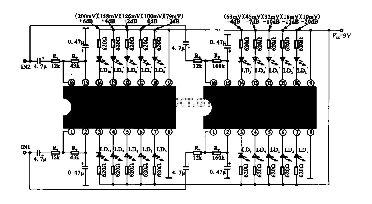
The circuit consists of dual drive integrated circuits (ICs) utilized in a 10 LED level meter configuration. The schematic features two TLM8101 driver ICs, which can be employed as alternatives. The 10 LED level meter circuit is designed to provide...