
18-bit ADC uses PC`s serial port

The described circuit allows a personal computer (PC) to interface directly with an 18-bit analog-to-digital converter (ADC), specifically the MAX132, through its RS-232 serial port. This design eliminates the need for a dedicated plug-in ADC card, thereby simplifying the hardware requirements for analog signal processing.
The MAX132 ADC operates with a serial interface and requires specific control signals to function correctly. These signals include Data Input (DIN), Serial Clock (SCLK), and End-of-Conversion (EOC). The ADC outputs serial data (DOUT) which contains the digital representation of the analog input signal. The EOC signal indicates when the conversion process is complete, allowing the microcontroller or PC to read the output data.
The RS-232 serial port provides three essential output lines: TX (Transmit), DTR (Data Terminal Ready), and RTS (Request to Send). The TX line is responsible for generating the clock signal necessary for the ADC operation while also supplying the negative voltage required for the MAX132. The DTR line is utilized to transmit the actual serial data from the ADC, while the RTS line serves a dual purpose: it provides the Chip Select (CS) signal and supplies the positive voltage to the ADC.
Power management is critical in this design, and large capacitors are employed to store energy for both the positive and negative power supplies. This configuration ensures that when the TX line generates a clock signal or when the DTR line sends a logic-low signal for the CS, the stored energy in the capacitors is readily available to power the MAX132, thus maintaining stable operation.
The MAX132 requires a reference voltage to ensure accurate conversion of the analog input signal. This reference voltage is provided by a 1.2V LM385 voltage-reference diode (D1), which ensures that the ADC operates within its specified input voltage range of -512 to +512 mV. This range allows for a wide variety of analog signals to be accurately digitized.
In summary, this circuit design effectively utilizes the capabilities of the MAX132 ADC in conjunction with the RS-232 serial port of a PC, enabling efficient analog signal processing without the need for additional hardware components. The integration of power management and reference voltage ensures reliable operation and accurate data conversion, making this an elegant solution for interfacing analog signals with digital systems.A PC usually requires a plug-in ADC card to process analog signals. However, with the circuitry in Figure 1, a PC can communicate with an 18-bit ADC through its serial port. The port provides both positive and negative power supplies as well as control signals. IC1 is an 18-bit MAX132 ADC with a serial interface. It requires three input control signals, , DIN, and SCLK, and emits serial data, DOUT, and EOC (end-of-conversion) signals.
An RS-232 port has three output lines: Pin 3 (TX), Pin 4 (DTR), and Pin 7 (RTS). TX generates the clock signal for the MAX132 and provides the negative power supply. DTR transmits serial data. RTS provides the CS signal and the positive power supply. Both the positive and the negative supplies use large capacitors for energy storage. When TX generates a clock signal or DTR sends a CS logic-low signal, the capacitors provide power to the MAX132. The MAX132 integrates everything except a reference that comes from a 1.2V LM385 voltage-reference diode, D1.
The input-voltage range of the MAX132 is -512 to +512 mV. Listing 1 is a C program that displays the analog-to-digital-conversion result on-screen.
Related Circuits

The hypnosis massage device is a compact electronic timing circuit that utilizes two 555 timers to address the health needs of individuals seeking relaxation. The circuit comprises three main components: a timer circuit, a hypnosis circuit, and a massage...
A 1999 Chevrolet Suburban has non-functional headlights. The fuses and circuit breakers have been checked and found to be operational. According to the owner's manual, the headlamps are protected by a circuit breaker located within the lamp switch, but...
Microchip has addressed the need for memory solutions with a comprehensive range of serial EEPROMs, available in various memory configurations and utilizing standard 2- or 3-wire communication protocols. The following assembly code outlines the procedure for writing and reading...
A portable FM transmitter that can be used to replace an FM microphone. This simple transmitter operates from a 9V battery. The old FM mic system was not a perfect solution, so a kit was built with a mixer...
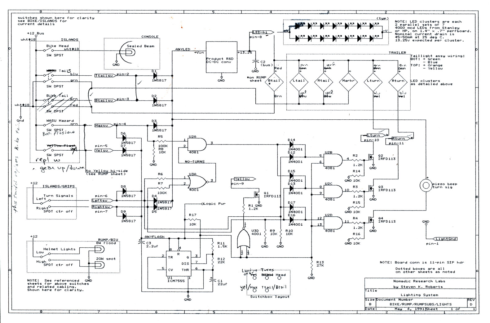
This second issue of the Bikelab Notes, published during the development of BEHEMOTH at Sun Microsystems, focuses on high-brightness LED taillight assemblies that were not commercially available at the time, making this a unique project. The author also comments...

The circuit features a frequency response ranging from 100 Hz to 3 MHz, with a gain of approximately 30 dB. Field-effect transistor Q1 is configured in a common-source self-biased mode. An optional resistor R1 allows for the adjustment of...