
555 consisting of portable electronic timing hypnosis massage

The hypnosis massage device employs two 555 timer ICs configured in astable and monostable modes to generate specific timing intervals. The first 555 timer operates in astable mode, producing a continuous square wave output that serves as the clock signal for the second timer. This clock signal can be adjusted by varying the resistor and capacitor values connected to the 555 timer, allowing users to customize the frequency and duration of the relaxation periods.
The second 555 timer is configured in monostable mode, triggered by the output of the first timer. This timer generates a single pulse of a predetermined duration whenever it receives a trigger signal. The output pulse can be used to activate a massage motor or other therapeutic devices, providing a timed massage experience.
The circuit is designed to be compact and portable, making it suitable for personal use. It can be powered by a small battery, ensuring convenience and ease of use. Additionally, the circuit can be integrated with other components, such as LED indicators or audio signals, to enhance the user experience.
In summary, the hypnosis massage device combines two 555 timers to create a versatile timing circuit that meets the relaxation needs of users through adjustable timing intervals for massage therapy. The design emphasizes portability and user customization, making it an effective tool for personal health and wellness. As shown in FIG hypnosis massage is pocket-sized electronic timing circuit with two 555 timers to form, to meet the health needs of people to relax. Circuit consists of three p arts: a timer circuit, a circuit hypnosis, massage circuit.
Related Circuits
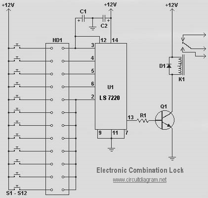
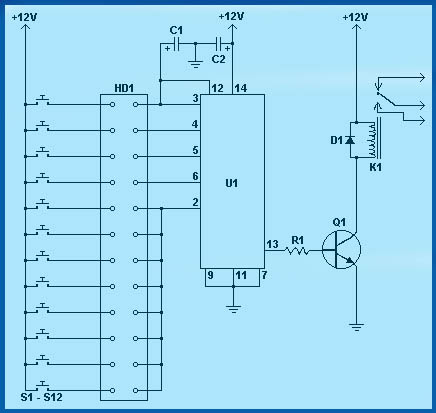
The following diagram illustrates a simple electronic combination lock based on the IC LS7220. The component part list includes: C1 = 1µF 25V, C2 = 220µF 25V, R1 = 2.2K Ohm, Q1 = 2N3904 or 2N2222, D1 = 1N4148...
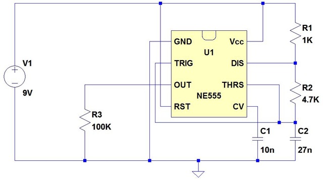
Input values for R1, R2, and C, then press the calculate button to determine the positive time interval (T1) and negative time interval (T2). For instance, using a 10K resistor (R1) and a 100K resistor (R2) along with a...
Circuit diagram schematics of electronic keys, electronic locks, digital electronic locks, transistor code locks, and combination electronic locks. The circuit schematics for electronic locking mechanisms encompass a variety of designs tailored to enhance security and convenience in access control systems....
The issue began when a girlfriend expressed her frustration with mosquitoes disrupting her nights. It was recognized that mosquito sprays provide only temporary relief, as the insects tend to return after some time. A suggestion was made for an...
The 555 timer generates positive pulses. The pulse width is inversely proportional to the difference in voltage between the "ANALOG IN" voltage and the voltage across a 4.7 µF capacitor (approximately 2.5 volts). To calibrate this circuit, connect it...
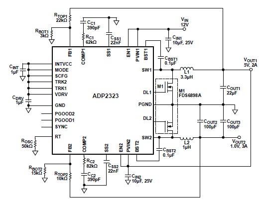
The ADP2323 DC-DC converter is designed to deliver two output voltages with specified maximum output currents. The first channel provides a 5-volt output with a maximum current of 2 Amperes, while the second channel supplies 1 volt with a...