
18 stage led sequencer
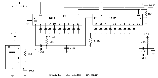
The circuit described involves a reset mechanism for counters, utilizing a combination of passive and active components to ensure proper initialization upon power-up. The 15KΩ resistor and 10µF capacitor connected to pin 15 create a time constant that governs the duration of the reset signal. Upon application of power, the capacitor begins to charge through the resistor, causing the voltage at pin 15 to rise. This action effectively resets the counters, setting pin 3 to +12V while all other outputs are held at zero.
The inclusion of the two 1N914 diodes and a 15Ω resistor forms an AND gate configuration, which is critical for controlling the passage of the clock pulse to the right side counter. The diodes ensure that the clock pulse is only transmitted when both inputs are high, thus preventing erroneous counting due to noise or unintended signals. The 15Ω resistor limits the current flowing through the diodes, protecting them from potential damage and ensuring stable operation.
Overall, this circuit design is a typical example of using a combination of resistors, capacitors, and diodes to achieve reliable counter operation in digital electronics. The careful selection of component values and configurations allows for precise control over the timing and logical operations required for effective counting sequences.When power is applied, the 15K resistor and 10uF cap at pin 15 will reset the counters to the zero count where pin 3 is at +12 and all other outputs are at zero. The 2 diodes (1n914) and 15 resistor form a AND gate so the clock pulse will be passed to the right side counter when the sequence starts..
🔗 External reference
Related Circuits
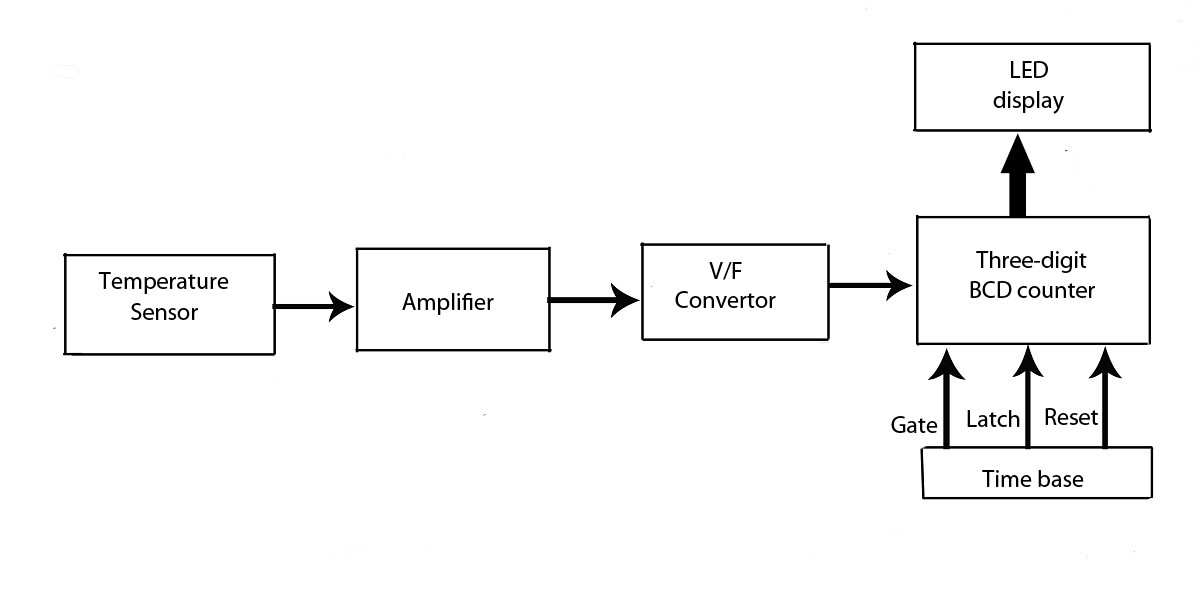
This verified project provides an idea, circuit, and operation of the LED display temperature indicator. It features a digital temperature indicator utilizing a voltage-to-frequency (V/F) converter, along with various electronic projects. The LED display temperature indicator is designed to provide a...
The last installment in this series (LEDs 102 - Use On Board Trains) concluded with some thoughts on how to turn battery-powered LEDs on and off. This article will explore various options for controlling LEDs and other devices on...
The motion games on the Nokia 5800 sparked an interest in creating a real-world version of a racing car controlled by tilting a phone. The motion-controlled robot, named Hercules due to its high torque and speed, is operated via...
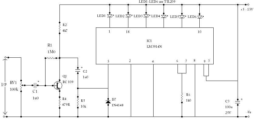
The circuit utilizes an LM3914N bar graph display driver (IC1) to control up to ten LEDs. It is configured such that when 0V is applied to the input, only the first LED indicator lights up. This straightforward peak reading...
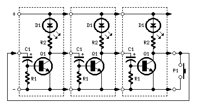
The purpose of this circuit is to create a ring in which LEDs or lamps illuminate sequentially. Its main feature is high versatility; a loop containing any number of LEDs or lamps can be built, as each illuminating device...
Many modern audio recorders are now compatible with digital input S/PDIF (Sony/Philips Digital Interface). Devices like CD changers, MiniDisc recorders, computer sound cards, and the like work with digital signals using the S/PDIF protocol. This digital connection between two...